
Lathe center

A tip and lathe technology, which is applied in the direction of tailstock / tip, turning equipment, tool holder accessories, etc., can solve the problems of reducing actual work efficiency, inconvenient use, troublesome clamping, etc., and achieve the effect of improving processing speed and quality

Inactive Publication Date: 2016-03-23
张俊锋
View PDF0 Cites 5 Cited by
  • Summary
  • Abstract
  • Description
  • Claims
  • Application Information

AI Technical Summary

Problems solved by technology

[0002] When processing small shaft parts on ordinary lathes, in order to improve the processing quality and speed, the two ends of the shaft to be processed are often used, that is, a top end is inserted into the spindle hole of the lathe to support the left end of the shaft to be processed, and the tailstock of the lathe is used. The top is against the right end of the processed shaft, and the processing is carried out by using the chicken heart clamp to transmit the torque. Although this processing method can be positioned at one time, the processed shaft does not need to be turned around, but the chicken core clamp is stuck to the processed shaft. The outer diameter transmits torque, and the clamping is troublesome. Every time a shaft is processed, it must be stopped for clamping and disassembly, so it is not convenient to use, which increases the labor intensity of the operator and reduces the actual work efficiency.

Method used


Image

  • Lathe center

Examples


Embodiment Construction

[0007] The present invention will be described in further detail below in conjunction with the accompanying drawings and embodiments.

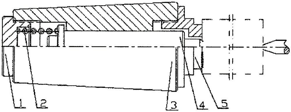
[0008] see figure 1 , a lathe top, including a screw plug 1, a spring 2, a Morse cone 3, a mandrel top 4 and an end-face sharp-toothed claw 5, the screw plug 1 is connected to the left end of the Morse cone 3 in a threaded manner, and the end-face sharp teeth The claw 5 is connected to the right end of the Morse cone 3 in a threaded manner, and the diameter of the right end surface of the toothed claw 5 is 5mm smaller than the diameter of the workpiece, and sharp teeth are set on the end surface, and the inner hole of the Morse cone 3 is movable. The mandrel top 4 is set in the same way, and the spring 2 is pressed between the screw plug 1 and the shoulder of the mandrel top 4 .

[0009] During processing, first insert the Morse cone 3 of the present invention in the lathe spindle hole, then align the center hole of the left end of the workpi...


PUM


Abstract

The invention discloses a lathe center. The lathe center comprises a plug screw, a spring, a Mohs taper, a mandrel center and an end face sharp tooth pusher dog; the plug screw is connected to the left end of the Mohs taper in a threaded manner, the end face sharp tooth pusher dog is connected to the right end of the Mohs taper in a threaded manner, and the diameter of the right end face of the end face sharp tooth pusher dog is 2 mm to 5 mm smaller than the diameter of a workpiece; sharp teeth are arranged on the end face of the end face sharp tooth pusher dog, and the mandrel center is arranged on an inner hole of the Mohs taper in a movable fit manner; and the spring is installed between the plug screw and a shaft shoulder of the mandrel center in a press fitting manner. By means of the lathe center, no-shutdown end face pulling is achieved, centering and pulling are combined, and the machining speed and quality are greatly improved.

Description

technical field [0001] The invention belongs to the technical field of machining fixtures, in particular to a lathe top. Background technique [0002] When processing small shaft parts on ordinary lathes, in order to improve the processing quality and speed, the two ends of the shaft to be processed are often used, that is, a top end is inserted into the spindle hole of the lathe to support the left end of the shaft to be processed, and the tailstock of the lathe is used. The top is against the right end of the processed shaft, and the processing is carried out by using the chicken heart clamp to transmit the torque. Although this processing method can be positioned at one time, the processed shaft does not need to be turned around, but the chicken core clamp is stuck to the processed shaft. The outer diameter transmits torque, and the clamping is troublesome. Every time a shaft is processed, it needs to be stopped for clamping and disassembly, so it is not convenient to use...

Claims


Application Information

Patent Timeline
Patent Type & Authority Applications(China)
IPC IPC(8): B23B23/00
CPCB23B23/005
Inventor 张俊锋
Owner 张俊锋
Learn More