
Chamfering mechanism

A chamfering mechanism and chamfering technology, applied in the field of mechanical equipment, can solve the problems of inability to be widely used, uneven chamfer size, difficult operation, etc., and achieve convenient chamfer control, uniform chamfer, and stable tool rotation. Effect

Active Publication Date: 2016-03-23
ZHUJI RUN TUO MECHANICAL AUTOMATION TECH
View PDF7 Cites 0 Cited by
  • Summary
  • Abstract
  • Description
  • Claims
  • Application Information

AI Technical Summary

Problems solved by technology

[0004] The above-mentioned scheme has improved some problems of the prior art to a certain extent, but there are at least the following defects in the scheme: the chamfering size is uneven, the precision is poor, and the operation is difficult when chamfering multiple workpieces at the same time, which cannot be widely used. Applications

Method used


Image

  • Chamfering mechanism
  • Chamfering mechanism
  • Chamfering mechanism

Examples


Embodiment Construction

[0022] The present invention will be further described in detail below in conjunction with the accompanying drawings and examples. The following examples are explanations of the present invention and the present invention is not limited to the following examples.

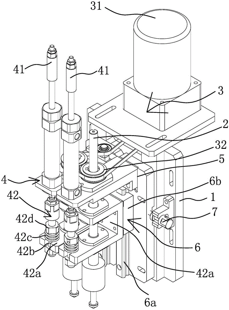
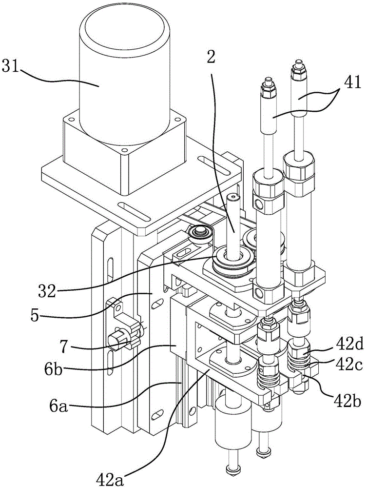
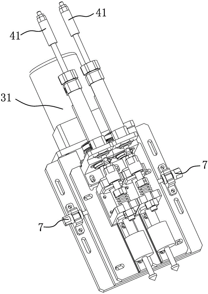
[0023] Such as Figures 1 to 4 As shown, the chamfering mechanism includes a frame 1, which is characterized in that: the frame 1 is provided with a chamfering drive mechanism 3 that simultaneously drives at least one cutter 2 to rotate, and each cutter 2 is respectively pierced with a 2 An elastic extrusion adjustment mechanism 4 that moves axially, one end of the elastic extrusion adjustment mechanism 4 is fixed on the frame 1, and the bottom of the elastic extrusion adjustment mechanism 4 is against the processing platform when chamfering It can greatly reduce the impact of the vibration caused by the rotation of the tool 2 on the machining accuracy of the workpiece during chamfering, so that the tool rotation is...


PUM


Abstract

The invention provides a chamfering mechanism and belongs to the field of mechanical equipment. The problem that design is not reasonable in the prior art is solved through the chamfering mechanism. The chamfering mechanism comprises a rack. A chamfering drive mechanism for driving at least one cutter to rotate simultaneously is arranged on the rack. Each cutter penetrates an elastic extrusion and adjustment mechanism capable of moving in the axial direction of the cutter. One end of each elastic extrusion and adjustment mechanism is fixed to the rack. The chamfering mechanism has the beneficial effects that design is more reasonable and the flexible axial adjustment mechanisms are arranged so that the chamfering size can be conveniently controlled, the cutters can rotate more stably, chamfering is even, and production efficiency is improved; due to the fact that each cutter is provided with the corresponding flexible axial adjustment mechanism, multiple workpieces can be chamfered at the same time while a single workpiece can be controlled to be subjected to different degrees of chamfering according to requirements, and the application range is enlarged; the distance between second installation seats with the cutters is adjusted so that multiple chamfering interval distances can be adjusted, and chamfering control is more convenient.

Description

technical field [0001] The invention belongs to the technical field of mechanical equipment, and in particular relates to a chamfering mechanism. Background technique [0002] There are usually burrs on the machined workpiece, which is not convenient for parts assembly. Therefore, chamfering is usually made on the end of the workpiece. An important function of chamfering is to remove burrs and make it easy to install. In addition, chamfering can also play a role It can be seen that the chamfering on the workpiece plays a very important role in reducing the stress concentration and strengthening the strength of the parts. However, the existing technology has the disadvantage of poor machining accuracy when chamfering and cannot perform chamfering on multiple workpieces at the same time. . [0003] In order to solve the problems existing in the prior art, people have carried out long-term exploration and proposed various solutions. For example, the Chinese patent literature ...

Claims


Application Information

Patent Timeline
Patent Type & Authority Applications(China)
IPC IPC(8): B23D79/00
Inventor 俞才王
Owner ZHUJI RUN TUO MECHANICAL AUTOMATION TECH
Learn More