An Efficient Machine Vision-Assisted Laser Processing Method

A machine vision and laser-assisted technology, applied in laser welding equipment, metal processing equipment, manufacturing tools, etc., can solve problems such as low efficiency, achieve high processing efficiency, save processing time, and facilitate pick-and-place effects

Active Publication Date: 2017-06-23
WUHAN LINGYUN PHOTOELECTRONICS SYST
View PDF2 Cites 2 Cited by
  • Summary
  • Abstract
  • Description
  • Claims
  • Application Information

AI Technical Summary

Problems solved by technology

[0016] The purpose of the present invention is to solve the problem of low efficiency in the prior art mentioned in the above-mentioned background technology, and to provide a highly efficient machine vision-assisted laser processing method

Method used


Image

  • An Efficient Machine Vision-Assisted Laser Processing Method
  • An Efficient Machine Vision-Assisted Laser Processing Method
  • An Efficient Machine Vision-Assisted Laser Processing Method

Examples


Embodiment 1

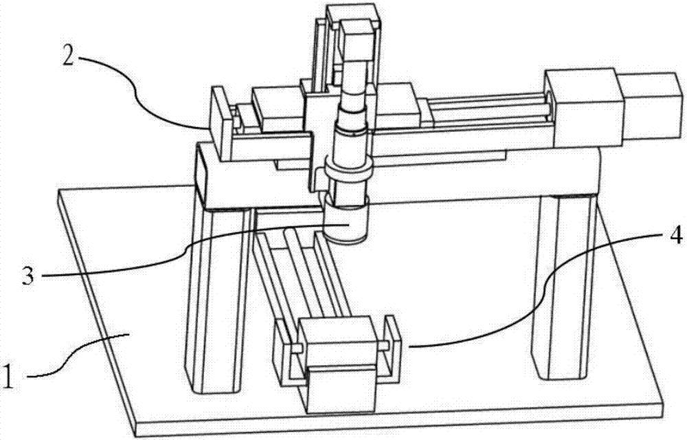
[0065] Embodiment 1: The upper end surface of the bottom plate 1 of this embodiment is provided with a plurality of jigs, each jig includes a component delivery track and a fixture that is slidably connected to the delivery track, and the fixture clamps the component through the motor or cylinder. The drive moves along the parts conveying track. Each part track includes two stations, namely the camera station and the processing station. Multiple parts conveying tracks are arranged side by side without intersecting each other.

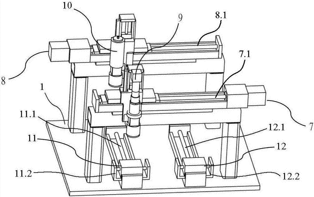
[0066] The first cylinder guide rail 7.1 and the second cylinder guide rail 8.1 are suspended above the parts conveying track, the first cylinder guide rail 7.1 conveys the camera 9 to switch between multiple camera stations, and the second cylinder guide rail 8.1 conveys the focusing head 10 in multiple Switch between processing stations.

[0067] Assuming that the number of component tracks is n, the number of corresponding imaging stations is also n,...

Embodiment 2

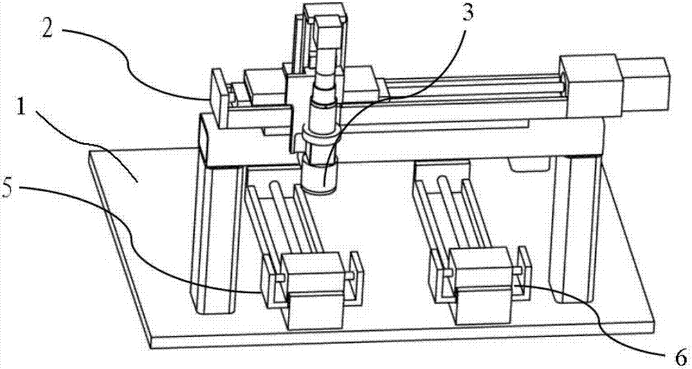
[0077] Embodiment 2: In this embodiment, only two sets of fixtures are set on the basis of Embodiment 1, such as image 3 The first jig 11 and the second jig 12 shown, the first jig 11 of this embodiment includes a first rail 11.1 fixed on the bottom plate 1 and a first jig 11.2 slidingly connected to the first rail 11.1, The second jig 12 includes a second rail 12.1 fixed on the bottom plate 1 and a second clamp 12.2 slidably connected to the rail. The first rail 11.1 and the second rail 12.1 are arranged parallel to each other in two three-axis linear displacements. under the table. The starting position of the first track 11.1 is the imaging station of the first fixture 11, that is, the first imaging station, and the end point is the processing station of the first fixture 11, that is, the first processing station, and the starting point of the second track 12.1 The position is the imaging station of the second jig 12, that is, the second imaging station, and the end point...


PUM


Abstract

The invention relates to the field of machine vision auxiliary positioning in laser machining, in particular to an efficient machine vision auxiliary laser machining method. According to the method, no less than two to-be-processed parts arranged on multiple stations in parallel are processed through a camera and a focusing head which are not coaxial, image information of the to-be-processed part at the first station of the multiple stations is collected through the camera, the part is machined through the focusing head soon afterwards according to the information, and image information collecting is carried out on the second part through the camera while the part is machined through the focusing head; after collecting is finished, image signal collecting is carried out on the third part, the second part is machined through the focusing head while collection is carried out, and machining of all the parts is synchronously completed sequentially and alternately. The camera and the focusing head are divided, it is guaranteed that the camera and the focusing head can be used at the same time, the waiting time of the main parts is shortened, the machining efficiency of the parts is improved, and the efficient machine vision auxiliary laser machining method has the extremely-large popularization value.

Description

technical field [0001] The invention relates to the field of machine vision-assisted positioning in laser processing, in particular to an efficient machine-vision-assisted laser processing method. Background technique [0002] Laser processing technology is one of the important aspects of laser application. The method of using laser technology to process consumer electronic products has been promoted more and more, and the rapid growth of current consumer electronic products makes such products have similar characteristics: being The shape of the processed parts is irregular, the size is small, there are gap errors in the installation of the fixture, and the automatic quality inspection and other problems. In the face of these problems, laser processing usually needs to be used in conjunction with machine vision to complete the precise processing process. Machine vision is used in laser processing for detection, positioning, defect judgment and other functions and provides d...

Claims


Application Information

Patent Timeline
Patent Type & Authority Patents(China)
IPC IPC(8): B23K26/03B23K26/70B23K26/08
CPCB23K26/032B23K26/08
Inventor 王锋汪建华林卿
Owner WUHAN LINGYUN PHOTOELECTRONICS SYST
Why Eureka
Try Eureka