Novel optical mold

An optical and mold technology, applied in the field of new optical molds, can solve problems such as affecting work efficiency, difficult to guarantee accuracy, and difficult to form, and achieve the effects of reducing material consumption, high precision, and improving yield

Inactive Publication Date: 2016-03-23
DONGGUAN HARMONY COOPERATION PLASTIC & HARDWARE TECH CO LTD
View PDF6 Cites 2 Cited by
  • Summary
  • Abstract
  • Description
  • Claims
  • Application Information

AI Technical Summary

Problems solved by technology

At this time, the hole with a depth of 60CM is required, and its accuracy is difficult to guarantee.
At the same time, the material consumption of the filling nozzle is more, and the heat dissipation speed is slower
For existing optical molds, if the runner and rubber channel are shortened, the temperature of the material will be relatively high when it reaches the product position, which will make it difficult to form and affect work efficiency.

Method used


Image

  • Novel optical mold
  • Novel optical mold
  • Novel optical mold

Examples


Embodiment Construction

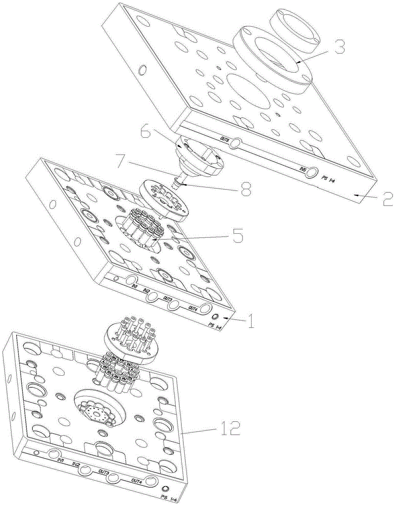
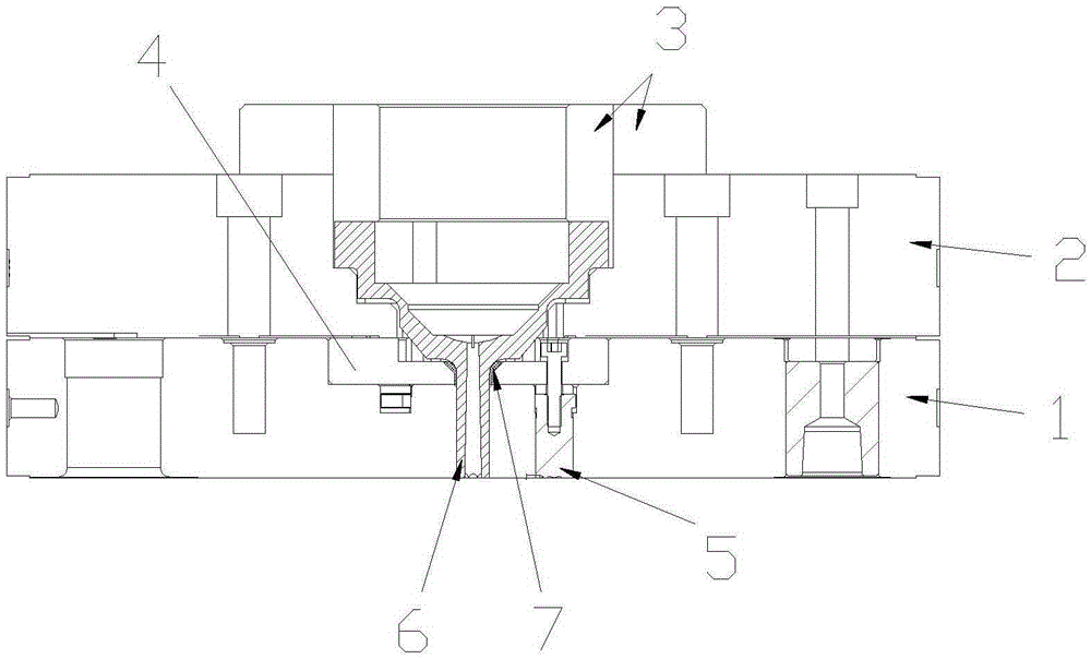
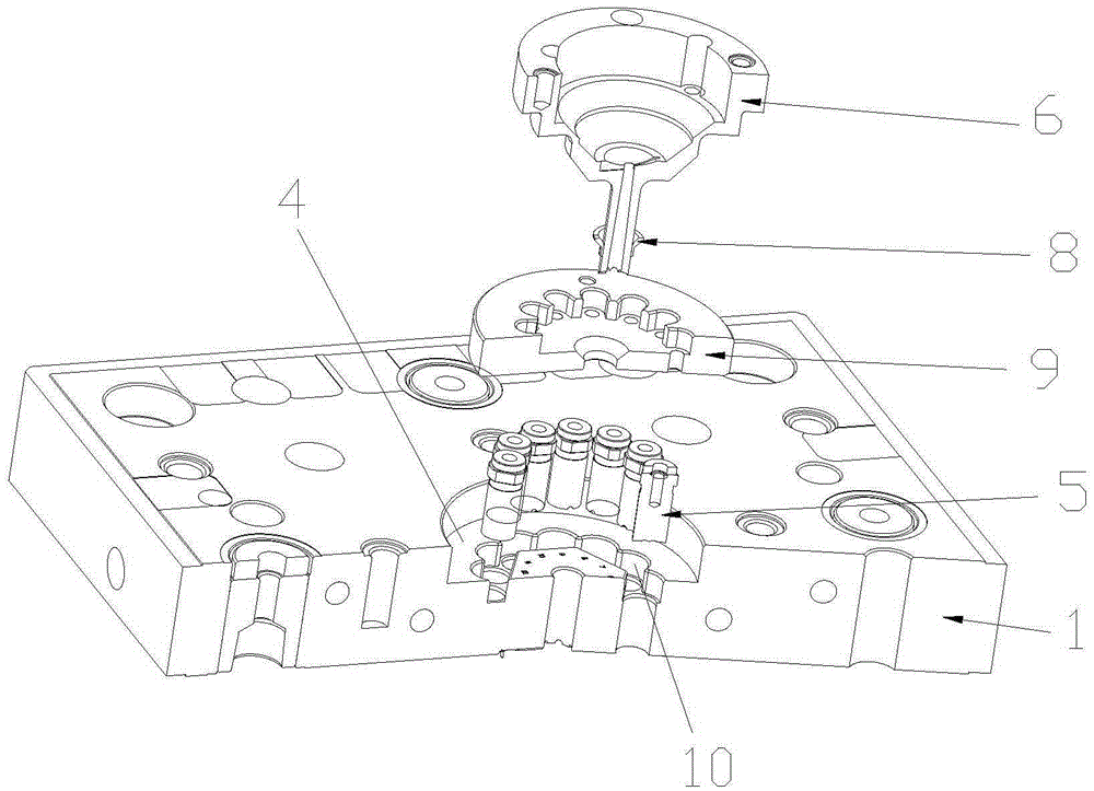
[0018] like Figure 1-Figure 4 As shown, a new type of optical mold includes a female template 1 and a male template 12. The female template 1 and the male template 12 are installed and fixed through the fixing plate 2 and the positioning ring 3. The bottom of the center of the female template 1 and the male template 12 is provided with Groove 4, spacer 9 is arranged in described hole groove 4, mold cavity 10 is respectively arranged in female template 1 and male template 12 below described hole groove 4, and described female template 1 and male template 12 are provided with A mold core 5, a filling nozzle 6 is arranged inside the master template 1 .

[0019] The mold core 5 is adapted to the mold cavity 10 .

[0020] The mold core 5 is compatible with the spacer 9 .

[0021] A glue channel 7 is arranged below the filling nozzle 6 .

[0022] A cooling sleeve 8 is provided outside the glue channel 7 .

[0023] When in use, the filling nozzle 6 is in contact with the nozzle ...


PUM


Abstract

The invention discloses a novel optical mold. The novel optical mold comprises a female mold plate and a male mold plate. Holes are formed in the bottoms of the centers of the female mold plate and the male mold plate. Cushion blocks are arranged inside the holes, mold cavities are formed in the parts, below the holes, of the female mold plate and the male mold plate respectively, mold cores are arranged inside the female mold plate and the male mold plate, and a pouring nozzle is arranged inside the female mold plate. The optical mold can keep machining precision of the mold cavities high, the pouring nozzle can effectively lower material consumption, and cooling speed is kept high and balanced.

Description

technical field [0001] The invention relates to a novel optical mold. Background technique [0002] The traditional injection molding mold is composed of a male mold and a female mold. The male mold and the female mold have a mold cavity that forms a certain shape of the product. After the mold is closed, the molten injection material enters the mold cavity of the mold and cools and hardens to the shape of the mold cavity. same product. There is a nozzle on the master mold, the main body of the nozzle is cylindrical, and one end has a nozzle head, which is used to cooperate with the nozzle of the injection molding machine, and the center of the nozzle has a conical main flow channel that runs through the nozzle. The injection plastic injected by the injection molding machine enters the main channel from the filling nozzle, and flows into the mold cavity through the main channel, or flows into the mold cavity through the branch channels of the main channel. After the main p...

Claims


Application Information

Patent Timeline
IPC IPC(8): B29C45/26
CPCB29C45/2602
Inventor 汪正国饶伟仝刚要袁超余俊齐耀平张小攀赵玉贵
Owner DONGGUAN HARMONY COOPERATION PLASTIC & HARDWARE TECH CO LTD
Why Eureka
Try Eureka