Power source used for electric vehicle

A technology for electric vehicles and power supplies, applied in electric vehicles, emergency power supply arrangements, current collectors, etc., can solve the problems of complicated wiring harness installation, complicated circuit diagrams, etc., to increase the number of charge and discharge cycles, avoid long-term work, and improve reliability. Effect

Inactive Publication Date: 2016-03-23
南京富道电子科技有限公司
View PDF8 Cites 8 Cited by
  • Summary
  • Abstract
  • Description
  • Claims
  • Application Information

AI Technical Summary

Problems solved by technology

Due to the existence of the battery, the DC-DC converter can be stopped when the vehicle is parked, but the charging process of the battery needs to be managed, otherwise there will be safety hazards, so the actual circuit will be more complex than figure 2 The schematic diagram of the circuit in is complicated, and at the same time, due to the increase of the battery, the installation of the wiring harness will also become complicated accordingly.

Method used


Image

  • Power source used for electric vehicle
  • Power source used for electric vehicle
  • Power source used for electric vehicle

Examples


Embodiment 1

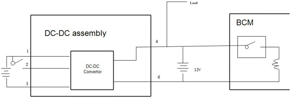
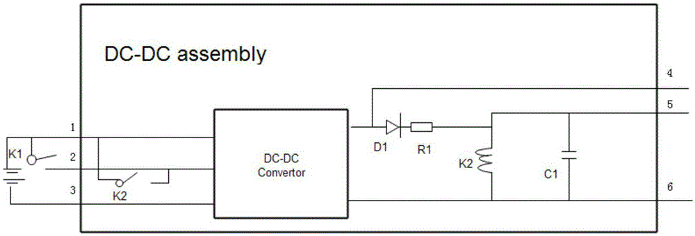
[0029] Such as image 3 As shown, the present invention is a power supply for electric vehicles, including a high-voltage battery V and a DC converter DC-DCassembly, the DC converter includes a power input positive terminal 1, a power input negative terminal 3, and is used to start the DC converter The enabling signal terminal 2 of the high-voltage battery v is electrically connected to the positive terminal 1 of the power input, the negative terminal of the high-voltage battery is electrically connected to the negative terminal 3 of the power input, and the positive terminal of the high-voltage battery is connected to A start control relay K1 is provided between the enabling signal terminals 2, wherein the DC converter DC-DCassembly includes a DC conversion module DC-DCconvertor, an equipment power supply output terminal 4, and a normal power supply output terminal 5. The power output terminal 5 can still provide power for the constant current equipment when the DC-DC convert...

Embodiment 2

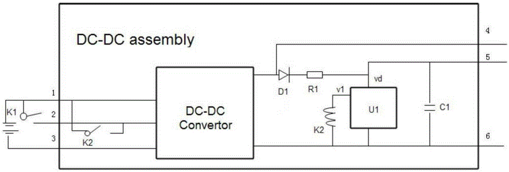
[0041] The difference between this embodiment and the first embodiment above is that a voltage detection unit U1 is further provided between the coil end of the built-in relay K2 and the output end 5 of the normal power supply.

[0042] The working principle of this embodiment:

[0043] The normal power output terminal 5 of the DC converter DC-DC assembly provides normal power for the start switch and alarm of the vehicle.

[0044] Electric vehicle starting state: at this time, the enable signal terminal 2 of the DC converter DC-DCassembly is controlled by high voltage, the DC conversion module DC-DCConvertor is in the working state, and the output terminal 4 of the equipment power supply of the DC converter DC-DCassembly is 12V The equipment provides power and the voltage is Vout; if the voltage of the capacitor C1 is lower than the set minimum working voltage Vout-0.7v, the DC conversion module DC-DCConvertor charges the capacitor C1 to Vc1=Vout-0.7 through the diode D1 and ...


PUM


Abstract

The invention provides a power source used for an electric vehicle. The power source comprises a high-voltage battery and a direct current converter. The direct current converter comprises a power source input anode end, a power source input cathode end, and an enable signal end used for starting the direct current converter. The anode end of the high-voltage battery is electrically connected with the power source input anode end. The cathode end of the high-voltage battery is electrically connected with the power source input cathode end. A start controlling relay is arranged between the anode end of the high-voltage battery and the enable signal end. The direct current converter comprises a direct current converting module, an equipment power supply power source output end, and a normal power source output end. The normal power source output end can still provide power for constant electric equipment under the condition that the direct current converting module does not work.

Description

technical field [0001] The invention relates to the field of automobile power supply control, in particular to a power supply of an electric vehicle. Background technique [0002] An electric vehicle is a complex system composed of multiple systems. In a pure electric vehicle, since a starter motor is not required, a 12V storage battery is theoretically not required. However, in the parking state, the vehicle's start switch, anti-theft alarm, etc. still need a standing 12V power supply to start the DC-DC converter and other low-voltage electrical equipment on the vehicle. [0003] In response to this requirement, there are two common solutions for pure electric vehicles. One of the options such as figure 1 As shown, the DC-DC converter is often connected to the main battery, and its output is used to supply power for constant current equipment, such as the start switch, and other low-voltage equipment is controlled by the relay of the start switch. However, in this solu...

Claims


Application Information

Patent Timeline
Patent Type & Authority Applications(China)
IPC IPC(8): B60L1/00B60L11/18H02J9/04
CPCY02T10/70
Inventor 席强李星
Owner 南京富道电子科技有限公司
Why Eureka
Try Eureka