Main generator excitation current variable level control circuit when the locomotive microcomputer excitation control fails

A main generator and excitation control technology, applied in the control drive, control device, power management and other directions, can solve the problems of low locomotive axle traction power, limited locomotive traction capacity, and inability to change the output power of the main generator, achieving traction The effect of increased capacity and maximized traction power

Active Publication Date: 2018-10-12
CRRC DALIAN CO LTD
View PDF4 Cites 0 Cited by
  • Summary
  • Abstract
  • Description
  • Claims
  • Application Information

AI Technical Summary

Problems solved by technology

[0004] In the fault excitation working condition of traditional diesel locomotives, only one or several fault excitation adjustment resistors are adjusted in the circuit. When the resistance value is fixed, the excitation current of the main generator has only a fixed value, which cannot be adjusted by the controller of the locomotive driver. and change, so that the output power of the main generator cannot be changed, the locomotive axle traction power is very small, and the traction capacity of the locomotive is severely limited

Method used


Image

  • Main generator excitation current variable level control circuit when the locomotive microcomputer excitation control fails

Examples


Embodiment Construction

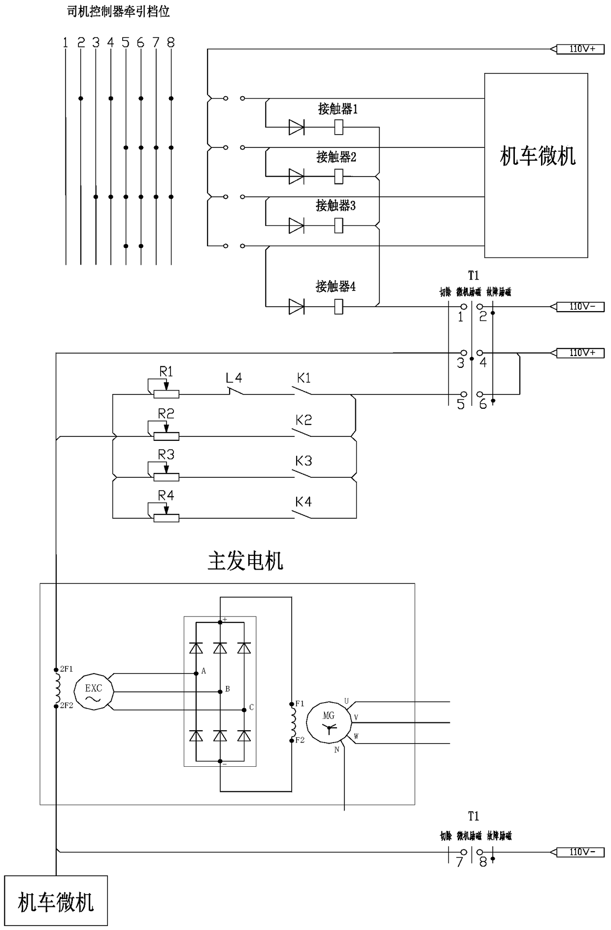
[0012] now attached figure 1 To further illustrate the present invention, the main generator of the CKD8G internal combustion locomotive is a brushless excitation generator, and its excitation current, under normal working conditions, is controlled by the power of the diesel engine at different handle speeds set by the locomotive microcomputer. The magnitude of the excitation current is adjusted and controlled. In the fault condition, it is adjusted and controlled by the fault excitation resistor.

[0013] (1) The locomotive microcomputer excitation, the handle of the excitation changeover switch T1 is set to the "microcomputer excitation" position. The locomotive auxiliary power supply 110VDC supplies power to the excitation winding of the brushless excitation main generator, and the locomotive microcomputer controls the average current of the field effect tube to meet the requirements of the locomotive.

[0014] (2) Locomotive fault excitation, the handle of the excitation...


PUM


Abstract

The invention discloses a main generator excitation current variable-level control circuit adopted when locomotive microcomputer excitation control fails. The control circuit comprises a locomotive microcomputer, a locomotive power system, a driver controller, a traction control circuit, a main generator microcomputer excitation loop and a main generator fault excitation loop. The driver controller is provided with a first traction gear, a second traction gear, a third traction gear, a fourth traction gear, a fifth traction gear, a sixth traction gear, a seventh traction gear and an eighth traction gear. A first contactor, a second contactor, a third contactor and a fourth contactor are connected to the traction control circuit. A locomotive fault excitation resistor R1, a locomotive fault excitation resistor R2, a locomotive fault excitation resistor R3 and a locomotive fault excitation resistor R4 are connected to the main generator fault excitation loop. A normally-open contact K1 of the first contactor, a normally-closed contact L4 of the fourth contactor and the locomotive fault excitation resistor R1 are sequentially connected in series and then connected with the locomotive power system. A normally-open contact K2 of the second contactor, a normally-open contactor K3 of the third contactor and a normally-open contact K4 of the fourth contactor are correspondingly connected with the locomotive fault excitation resistor R2, the locomotive fault excitation resistor R3 and the locomotive fault excitation resistor R4 in series respectively and then connected to the locomotive power system, the output power of a locomotive main generator can be adjusted under the fault excitation working condition, the traction power of a locomotive axle is maximal, and the traction capacity of a locomotive is greatly improved.

Description

technical field [0001] The invention relates to the technical field of excitation current of a main generator of a locomotive, in particular to a variable-level control circuit for the excitation current of a main generator when the excitation control of a locomotive microcomputer fails. Background technique [0002] The main transmission system of the CKD8G diesel locomotive adopts the "AC-DC" electric transmission mode. The output terminal of the diesel engine drives a three-phase AC power generated by a synchronous traction main generator, and the silicon rectifier device performs three-phase bridge full-wave rectification. The rectified The DC power is sent to six fully parallel DC traction motors through the main contactor and direction changeover switch, and then the traction motors drive the wheels to rotate through transmission gears. It can be seen that the locomotive main generator is the core equipment of the locomotive power system, and its working stability dire...

Claims


Application Information

Patent Timeline
Patent Type & Authority Patents(China)
IPC IPC(8): B60L15/22
CPCB60L15/22B60L2240/429Y02T10/72
Inventor 曲铁涛淡永宁王楠陈旭傅鑫
Owner CRRC DALIAN CO LTD
Why Eureka
Try Eureka