Novel intelligent stand column swing arm crane
A crane and column technology, applied in the field of new intelligent column swing arm crane, can solve the problems of limited lifting range, limited rotation range, single mechanism function, etc. Effect
- Summary
- Abstract
- Description
- Claims
- Application Information
AI Technical Summary
Problems solved by technology
Method used
Image
Examples
Embodiment 1
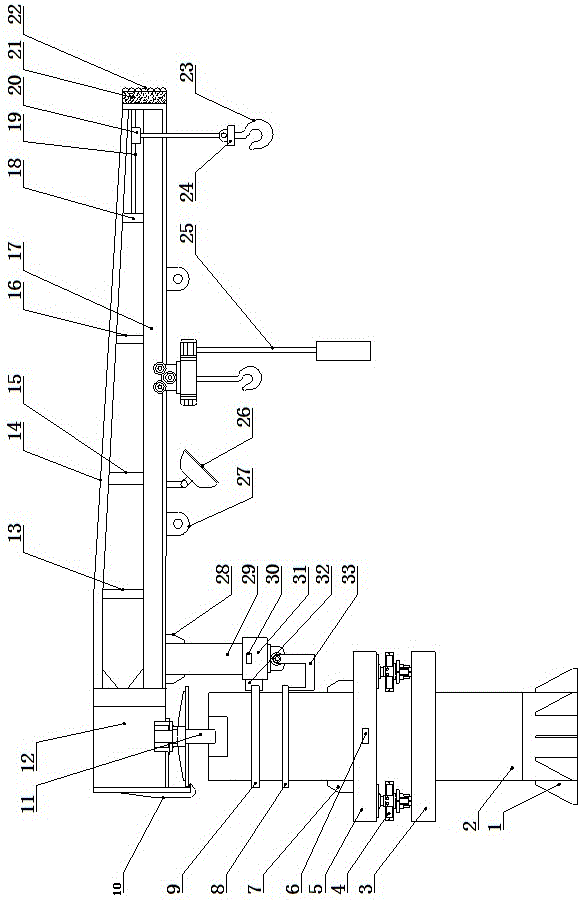
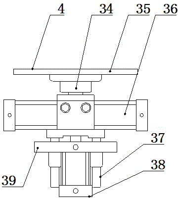
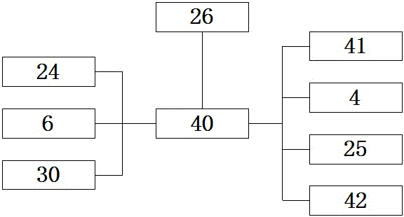
[0019] like Figure 1-3 As shown, a new type of intelligent column 2 swing arm crane, it includes a column 2, the outer side of the lower end of the column 2 is uniformly provided with a reinforcing plate 1, and the middle part of the column 2 is connected with a lower supporting plate in sequence from bottom to top 3 and the upper pallet 5, a jacking rotary table 4 is arranged between the lower pallet 3 and the upper pallet 5, an inclination sensor 6 is arranged in the upper pallet 5, and the upper pallet 5 A sub-plate 7 is arranged between the column 2, and the upper part of the column 2 is provided with a circular track 8 and a circular guide rail 9 in sequence from bottom to top. The top of the column 2 is connected to a rotating shaft 11, and the rotating shaft 11 The upper end is connected with a load-bearing box 12, the left end of the load-bearing box 12 is connected with a safety hook 10, the upper left end of the load-bearing box 12 is connected with a diagonal bar 1...
Embodiment 2
[0022] like Figure 1-3As shown, a new type of intelligent column 2 swing arm crane, it includes a column 2, the outer side of the lower end of the column 2 is uniformly provided with a reinforcing plate 1, and the middle part of the column 2 is connected with a lower supporting plate in sequence from bottom to top 3 and the upper pallet 5, a jacking rotary table 4 is arranged between the lower pallet 3 and the upper pallet 5, an inclination sensor 6 is arranged in the upper pallet 5, and the upper pallet 5 A sub-plate 7 is arranged between the column 2, and the upper part of the column 2 is provided with a circular track 8 and a circular guide rail 9 in sequence from bottom to top. The top of the column 2 is connected to a rotating shaft 11, and the rotating shaft 11 The upper end is connected with a load-bearing box 12, the left end of the load-bearing box 12 is connected with a safety hook 10, the upper left end of the load-bearing box 12 is connected with a diagonal bar 14...
PUM
 Abstract
Description
Claims
Application Information
 - R&D
- Intellectual Property
- Life Sciences
- Materials
- Tech Scout
- Unparalleled Data Quality
- Higher Quality Content
- 60% Fewer Hallucinations
Browse by: Latest US Patents, China's latest patents, Technical Efficacy Thesaurus, Application Domain, Technology Topic, Popular Technical Reports.
© 2025 PatSnap. All rights reserved.Legal|Privacy policy|Modern Slavery Act Transparency Statement|Sitemap|About US| Contact US: help@patsnap.com


