Automatic capping machine for plastic caps

A technology of plastic caps and capping machines, which is applied in the direction of flanged bottle caps, etc., can solve problems such as leakage of pressure, production pause, and insufficient compression, so as to avoid pressure leakage, increase the speed of capping, and increase the speed of capping. high effect

Inactive Publication Date: 2016-03-23
DANGSHAN XINYU IRON
View PDF0 Cites 2 Cited by
  • Summary
  • Abstract
  • Description
  • Claims
  • Application Information

AI Technical Summary

Problems solved by technology

[0002] Milk powder is generally packed in iron cans with good sealing performance, and iron cans generally need a plastic cover to seal the lid. In general capping machines, the conveyor belt drives the iron cans to move, and the belt in the middle of the can body stabilizes the position of the iron cans. , and then the plastic cover falls on the tank, and the plastic cover is compressed by a pneumatic or hydraulic pressure mechanism. However, if the plastic cover is slightly skewed or deformed when placed, it may cause pressure leakage or pressure. In addition, the compression of iron cans of different heights requires complex adjustments and even needs to change the production line, so continuous production cannot be carried out, and the plastic cap conveying channel of the existing capping machine is only slightly larger than the plastic cap. If the plastic cover is slightly deformed and twisted, it will block the conveying channel, causing production to stop

Method used


Image

  • Automatic capping machine for plastic caps
  • Automatic capping machine for plastic caps
  • Automatic capping machine for plastic caps

Examples


Embodiment

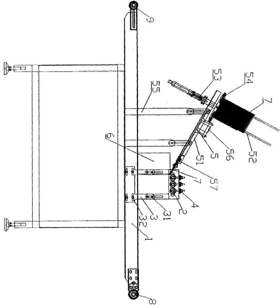
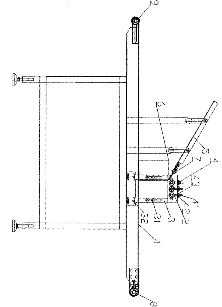
[0029] Such as Figure 1 ~ Figure 4 Shown: an automatic capping machine for plastic caps, including a pressing mechanism for pressing the plastic cap on the iron can; a conveying mechanism for transporting the plastic cap to the entrance of the pressing mechanism;

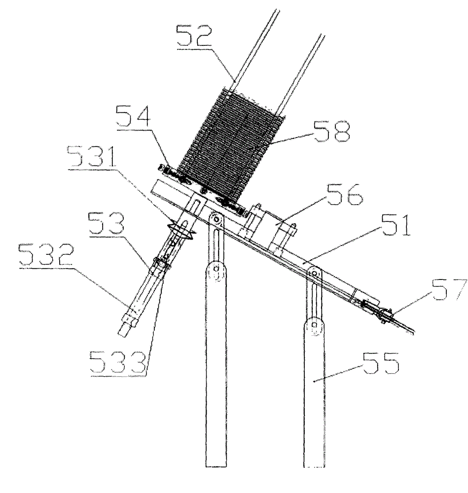
[0030] The conveying mechanism 5 includes a slideway 51 that allows the plastic cover 7 to slide to the plastic cover pressing mechanism, a cap loading mechanism 52 that can accommodate a plurality of plastic covers 7 above the front end of the slideway 51, and a cover loading mechanism 52 located on the top of the front end of the slideway 51. The bottom of the plastic cover 7 is sucked to the suction cup mechanism 53 on the slideway 51; the bottom of the cover loading mechanism 52 is also provided with a first spring mechanism for supporting the plastic cover 7. The cover loading mechanism 52 and the slideway 51 are arranged vertically, and the cover loading mechanism 52 and the suction cup mechanism 53 are arran...


PUM


Abstract

The invention discloses an automatic capping machine for plastic caps. The automatic capping machine is characterized by comprising a pressing mechanism which tightly presses the plastic caps on iron cans and a conveying mechanism which conveys the plastic caps to an inlet of the pressing mechanism, wherein the pressing mechanism can automatically adjust capping tightness degree according to bending deformation of the plastic caps through a spring mechanism capable of automatically adjusting tightness degree. Therefore, the phenomenon of missed capping is effectively avoided; the iron cans with various heights can be continuously produced; the conveying mechanism puts the plastic caps one by one in a sliding way for automatic gravitational conveying through a vacuum sucker; the whole conveying mechanism can rapidly and stably work; the requirement for flatness of the plastic caps is low, and conveying stop due to slight warping of the plastic caps is avoided.

Description

1. Technical field [0001] The invention belongs to the technical field of milk powder packaging equipment, and in particular relates to an automatic plastic cap capping machine for press-fitting a plastic cap and a milk powder tin can together. 2. Background technology [0002] Milk powder is generally packed in iron cans with good sealing performance, and iron cans generally need a plastic cover to seal the lid. In general capping machines, the conveyor belt drives the iron cans to move, and the belt in the middle of the can body stabilizes the position of the iron cans. , and then the plastic cover falls on the tank body, and the plastic cover is compressed by a pneumatic or hydraulic pressure mechanism, but if the plastic cover is placed slightly skewed or the plastic cover is deformed, it may cause pressure leakage or pressure. In addition, the compression of iron cans of different heights requires complex adjustments and even needs to change the production line, and con...

Claims


Application Information

Patent Timeline
IPC IPC(8): B67B3/06B67B3/10
Inventor 黄兴丽
Owner DANGSHAN XINYU IRON
Why Eureka
Try Eureka