A front outrigger structure of a highway bridge erection lifting device

A technology of lifting equipment and front outriggers, which is applied in the field of front outrigger structures, can solve problems such as uneven infrastructure, complex front outrigger structures, and unstable operation, and achieve high construction efficiency, improved operation adaptability, The effect of improving the lubrication effect

Active Publication Date: 2017-01-04
HENAN SINOKO CRANES
View PDF5 Cites 0 Cited by
  • Summary
  • Abstract
  • Description
  • Claims
  • Application Information

AI Technical Summary

Problems solved by technology

[0002] With the proposal and implementation of the grand development strategy of "One Belt, One Road" and "Maritime Silk Road", it will definitely bring a huge impetus to the development of countries and regions along the route. However, the infrastructure in various regions along the route is uneven. In particular, the weak infrastructure in some underdeveloped areas in the west will hinder various plans. Therefore, the premise of realizing this grand blueprint is to vigorously invest in and build infrastructure. In the process, road bridges and railway bridges must be There will be a lot of construction. In the construction process, bridge erecting equipment is an indispensable lifting equipment. The front outriggers of bridge erecting equipment are responsible for moving and supporting in the overall equipment, but most of the current front outriggers have structures It is more complicated, not stable enough during operation, and cannot meet the corresponding requirements of construction

Method used


Image

  • A front outrigger structure of a highway bridge erection lifting device
  • A front outrigger structure of a highway bridge erection lifting device

Examples


Embodiment 1

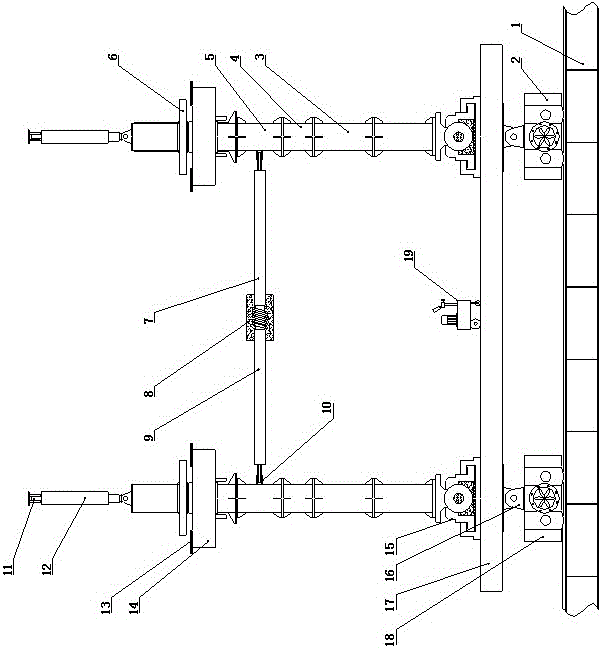
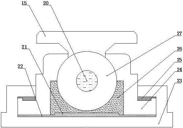
[0015] like figure 1 and figure 2 As shown, a front outrigger structure of a highway bridge lifting equipment, which includes a traversing track 1, and the left and right parts of the upper side of the traversing track 1 are connected with a driven wheel box 18 and a driving wheel box 2 in sequence. , the upper ends of the driving wheel box 2 and the driven wheel box 18 are connected with a saddle structure 16, the upper end of the saddle structure 16 is connected with a crossbeam 17, and the left and right sides of the upper end of the crossbeam 17 are connected with rotating The support 15, the middle part of the upper end of the beam 17 is provided with an oil pump 19, the upper end of the rotating support 15 is connected with a long standard section 3, and the upper end of the long standard section 3 is connected with a short standard section 4, The upper end of the short standard section 4 is connected with the middle standard section 5, and the inner side of the middle...

Embodiment 2

[0018] like figure 1 and figure 2 As shown, a front outrigger structure of a highway bridge lifting equipment, which includes a traversing track 1, and the left and right parts of the upper side of the traversing track 1 are connected with a driven wheel box 18 and a driving wheel box 2 in sequence. , the upper ends of the driving wheel box 2 and the driven wheel box 18 are connected with a saddle structure 16, the upper end of the saddle structure 16 is connected with a crossbeam 17, and the left and right sides of the upper end of the crossbeam 17 are connected with rotating The support 15, the middle part of the upper end of the beam 17 is provided with an oil pump 19, the upper end of the rotating support 15 is connected with a long standard section 3, and the upper end of the long standard section 3 is connected with a short standard section 4, The upper end of the short standard section 4 is connected with the middle standard section 5, and the inner side of the middle...


PUM


Abstract

The invention relates to a front supporting leg structure of novel highway bridging hoisting equipment. The front supporting leg structure of the novel highway bridging hoisting equipment comprises a transverse moving rail. The left and right portions of the upper surface of the transverse moving rail are sequentially connected with a driven wheel box and a driving wheel box. The upper ends of the driving wheel box and the driven wheel box are both connected with saddle structures. The upper ends of the saddle structures are connected with a cross beam, and the left and right sides of the upper end of the cross beam are both connected with rotary supports. A pull rod A and a pull rod B are connected between lug plates, and a buffering mechanism is arranged in the connecting position of the pull rod A and the pull rod B. A sphere body is arranged in the middle of each rotary support, an oil storage chamber is arranged inside each sphere body, an upper semi-spherical shell is arranged on the upper side of each sphere body, and a lower semi-spherical shell is arranged on the lower side of the sphere body. A pressed Teflon sliding plate is arranged on the lower side of each lower semi-spherical shell, a stainless steel plate is arranged on the lower side of each pressed Teflon sliding plate, and an anti-drawing Teflon sliding plate is arranged in the middle of the connecting position of a sliding box and each upper semi-spherical shell. The front supporting leg structure of the novel highway bridging hoisting equipment has the advantages of being simple in structure, stable in operation, high in construction efficiency and convenient and rapid to operate.

Description

technical field [0001] The invention belongs to the technical field of hoisting equipment, and in particular relates to a front outrigger structure of hoisting equipment for road bridge erection. Background technique [0002] With the proposal and implementation of the grand development strategy of "One Belt, One Road" and "Maritime Silk Road", it will definitely bring a huge impetus to the development of countries and regions along the route. However, the infrastructure in various regions along the route is uneven. In particular, the weak infrastructure in some underdeveloped areas in the west will hinder various plans. Therefore, the premise of realizing this grand blueprint is to vigorously invest in and build infrastructure. In the process, road bridges and railway bridges must be There will be a lot of construction. In the construction process, bridge erecting equipment is an indispensable lifting equipment. The front outriggers of bridge erecting equipment are responsi...

Claims


Application Information

Patent Timeline
Patent Type & Authority Patents(China)
IPC IPC(8): E01D21/00
Inventor 崔丽郭仕超胡哲涛刘继伟
Owner HENAN SINOKO CRANES
Why Eureka
Try Eureka