
Spiral flow shaft type energy dissipation drop well

A water drop well and shaft type technology, which is applied in the field of swirl shaft energy dissipation drop wells, can solve the problems of affecting the appearance, increasing the number of water drop wells, and large investment, and achieves the effect of wide application range and reduced floor space

Active Publication Date: 2016-03-23
CHINA RAILWAY SIYUAN SURVEY & DESIGN GRP
View PDF13 Cites 16 Cited by
  • Summary
  • Abstract
  • Description
  • Claims
  • Application Information

AI Technical Summary

Problems solved by technology

In areas where the height difference between the upstream and downstream of the drainage pipe exceeds 6m, or where the diameter of the drainage pipe is greater than 200mm, 400mm, or 1500mm, there is no standard drawing for the existing drop wells, and the diameter and drop difference of the above three drop wells are restricted. , the scope of use is limited, and in some places it may be necessary to use multi-stage water drop, which not only increases the number of water drop wells, but also requires a large investment, occupies a large area, and also affects the appearance
[0003] At present, deep tunnel drainage projects are planned and constructed in large cities in my country. They are used to collect rain and sewage in the city center and transport them to sewage treatment plants in the suburbs for centralized treatment. 1. Sewage is introduced into the deep tunnel, and it is required to have the functions of receiving pipelines, falling water, energy dissipation, and exhausting energy. However, the existing falling water wells cannot effectively solve the functions of water falling, energy dissipation, and exhausting at the same time.

Method used


Image

  • Spiral flow shaft type energy dissipation drop well
  • Spiral flow shaft type energy dissipation drop well
  • Spiral flow shaft type energy dissipation drop well

Examples


Embodiment Construction

[0020] The following will clearly and completely describe the technical solutions in the embodiments of the present invention with reference to the accompanying drawings in the embodiments of the present invention. Obviously, the described embodiments are only some, not all, embodiments of the present invention. Based on the embodiments of the present invention, all other embodiments obtained by persons of ordinary skill in the art without making creative efforts belong to the protection scope of the present invention.

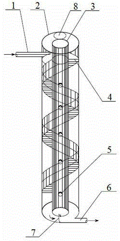
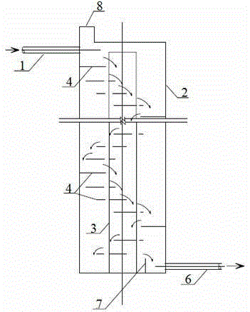
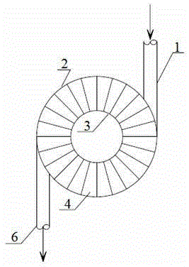
[0021] Such as Figure 1-Figure 3 , the embodiment of the present invention provides a swirl shaft type energy dissipation drop well, including an inner shaft 3 and an outer shaft 2, the upper part of the outer shaft 2 is connected with a water inlet pipe 1, and the lower part of the outer shaft 2 is connected with a water outlet pipe 6, The inner wellbore 3 and the outer wellbore 2 form an annular swirl space, and in the annular swirl space, a plurality of pa...


PUM


Abstract

The invention relates to a spiral flow shaft type energy dissipation drop well, which comprises an inner shaft and an outer shaft, wherein a water inlet pipe is connected to the upper part of the outer shaft and a water outlet pipe is connected to the lower part of the outer shaft; an annular spiral flow space is surrounded by the inner shaft and the outer shaft; and a plurality of partition boards are distributed inside the annular spiral flow space from top to bottom in a spiral mode, so that a spiral flow drainage passage is formed. By virtue of the partition boards which are distributed in a spiral mode as well as the walls of the outer shaft and the inner shaft, the flow direction of water is changed so as to reduce the flow rate of the water, so that the purposes of energy dissipation and water dropping are achieved; problems, which are solved in plane, are solved in a vertical direction, so that the occupied area of project is reduced. The drop well provided by the invention is not limited by a drop difference and the diameter of the water inlet pipe; and the drop well is broad in application scope, and is applicable to rainwater and sewage pipeline network works in such construction industries as municipal administration, railway, petroleum, water conservancy and the like.

Description

technical field [0001] The invention belongs to the technical field of drainage engineering, and in particular relates to a swirl shaft type energy dissipation drop well, which is suitable for drainage engineering in municipal, railway, electric power, water conservancy and other industries. Background technique [0002] There are only three types of drop wells in the municipal, railway, electric power, water conservancy, construction and other industries: vertical pipe type, vertical trough type and stepped type. The energy of water serves the purpose of energy dissipation. According to the national standard diagram, it is suitable for situations where the diameter of the water inlet pipe is not greater than 200mm and the drop of the pipe is less than 6m; , to reduce the energy of water and achieve the purpose of energy dissipation. According to the national standard diagram, it is applicable to the situation where the diameter of the pipe is not greater than 400mm and the ...

Claims


Application Information

Patent Timeline
IPC IPC(8): E03F5/02
CPCE03F5/02E03F5/022
Inventor 王松林杜永新王忠合刘佳蒋金辉温智勇
Owner CHINA RAILWAY SIYUAN SURVEY & DESIGN GRP
Learn More