
Unit panel for spherical shape building and its application method

A unit panel and construction technology, applied to the processing of building materials, construction, building components, etc., can solve the problems of high labor and material costs, troublesome trapezoidal straight panel processing, and complicated spherical panel molding, so as to achieve simple structure and improve stability. And safety, waterproof, reliable and effective effect

Inactive Publication Date: 2017-10-10
四川盛邦建设工程有限公司
View PDF6 Cites 0 Cited by
  • Summary
  • Abstract
  • Description
  • Claims
  • Application Information

AI Technical Summary

Problems solved by technology

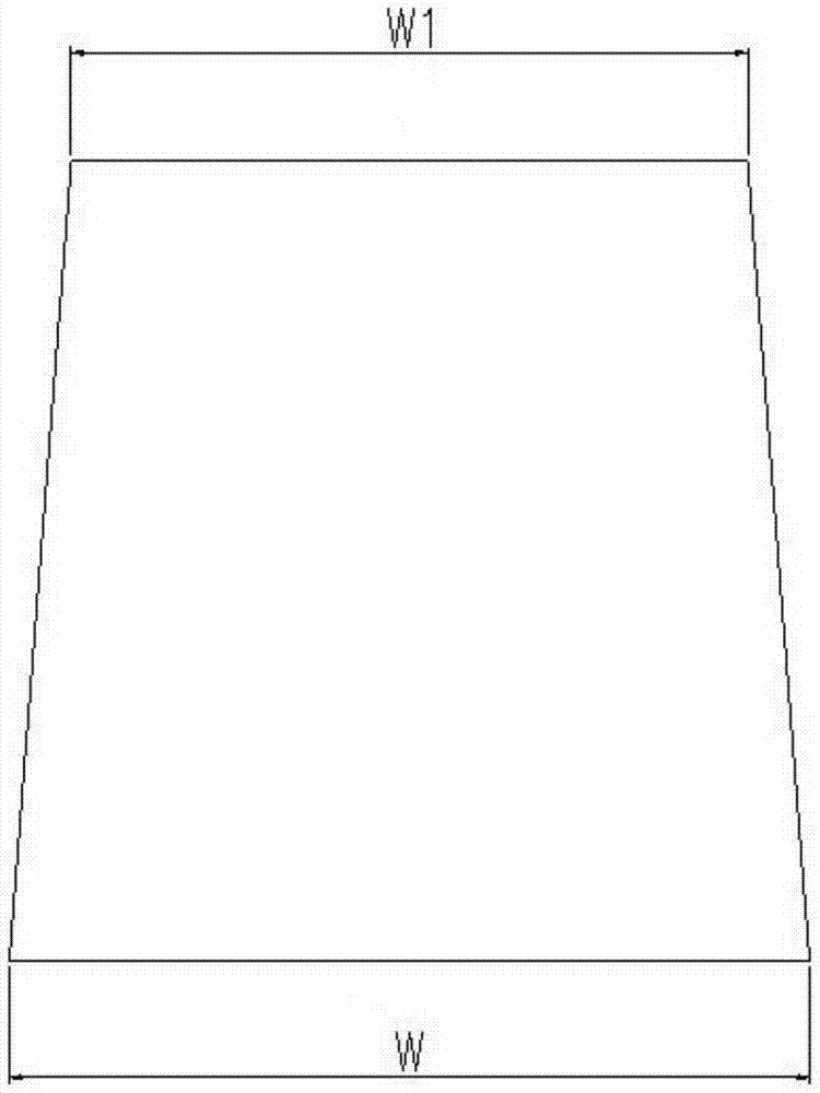
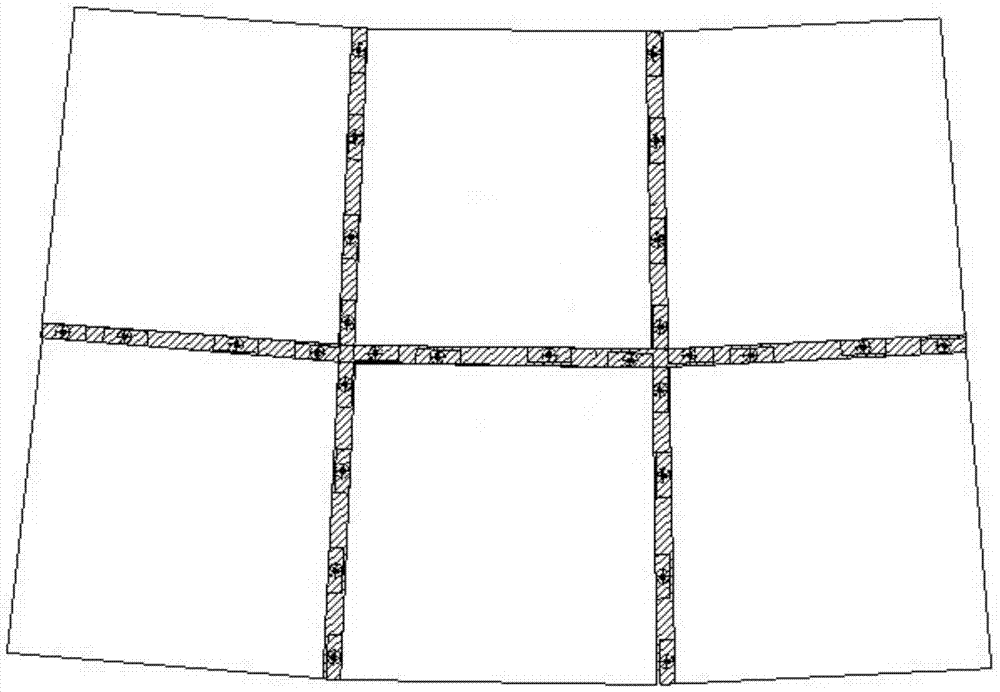
In the prior art, one way of building a spherical shape is to process the surface of the panel to better simulate the shape of the surface. However, the shape of the spherical plate is complex and difficult, and it is necessary to customize a variety of mold tires. The irregular spherical plate Compared with standard parts, the installation is complicated and time-consuming, and the overall labor and material costs are relatively high; another way is to splice small pieces of straight panels into a spherical shape, such as figure 1 , 2 As shown, usually trapezoidal straight panels are used for splicing, and the splicing gap is waterproofed by glueing. In the prior art, trapezoidal straight panels are used for splicing. Calculate the upper width W1 and the lower width W value of the trapezoidal straight board. A large spherical building needs trapezoidal straight boards of various specifications for splicing. It is necessary to calculate multiple W1 and W values ​​before processing and customizing, resulting in increased costs.
The second is that the splicing gap is waterproofed by glue. Due to the thermal expansion and contraction of the building, as well as the erosion of sunlight and rain, the glue will age and cause water leakage in the building. There are hidden dangers of water leakage and the overall structure is not firm.

Method used


Image

  • Unit panel for spherical shape building and its application method
  • Unit panel for spherical shape building and its application method
  • Unit panel for spherical shape building and its application method

Examples


Embodiment 1

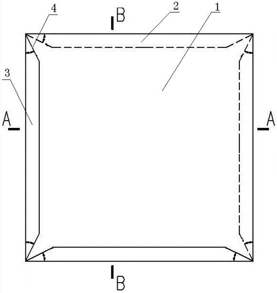
[0022] Such as Figure 3-6 As shown, a unit panel for a spherical shape building includes a rectangular panel 1, wherein two adjacent edges of the rectangular panel 1 are respectively provided with inwardly turned inner folds 2 along a direction perpendicular to the rectangular panel 1, and the other two Edges perpendicular to the direction of the rectangular plate 1 are respectively provided with outwardly turned outward flanges 3, the angles formed by the inner flange 2, the outer flange 3 and the rectangular plate 1 are all 50°, and the inner flange 2, The width of the outer flange 3 is 10 mm, the angles formed by the inner flange 2, the outer flange 3 and the rectangular plate 1 and the width of the fold are consistent, and the inner flange 2 and the outer flange 3 are occluded when the rectangular plate 1 is spliced. The snap-on connection is secure.

[0023] Further, chamfers 4 are respectively provided at both ends of the inner folds 2 and the outer folds 3 to prevent ...

Embodiment 2

[0029] Such as Figure 3-6 As shown, a unit panel for a spherical shape building includes a rectangular panel 1, wherein two adjacent edges of the rectangular panel 1 are respectively provided with inwardly turned inner folds 2 along a direction perpendicular to the rectangular panel 1, and the other two Edges are perpendicular to the rectangular plate

[0030] 1 direction is respectively provided with the outer flange 3 turned outwards, the included angles formed by the inner flange 2, the outer flange 3 and the rectangular plate 1 are all 60°, the inner flange 2, the outer flange 3 The width is 15mm, the inner fold 2, the outer fold 3 are formed with the rectangular plate 1

[0031] The included angles and the widths of the folds are consistent, and the inner fold 2 and the outer fold 3 of the rectangular plate 1 are fastened and fastened firmly when spliced.

[0032] Further, chamfers 4 are respectively provided at both ends of the inner folds 2 and the outer folds 3 to a...

Embodiment 3

[0040] Such as Figure 3-6 As shown, a unit panel for a spherical shape building includes a rectangular panel 1, wherein two adjacent edges of the rectangular panel 1 are respectively provided with inwardly turned inner folds 2 along a direction perpendicular to the rectangular panel 1, and the other two Edges perpendicular to the direction of the rectangular plate 1 are respectively provided with outwardly turned outward flanges 3, the angles formed by the inner flange 2, the outer flange 3 and the rectangular plate 1 are all 70°, and the inner flange 2, The width of the outer flange 3 is 20mm, the angles formed by the inner flange 2, the outer flange 3 and the rectangular plate 1 and the width of the fold are consistent, and the inner flange 2 and the outer flange 3 are occluded when the rectangular plate 1 is spliced. The snap-on connection is secure.

[0041] Further, chamfers 4 are respectively provided at both ends of each inner flange 2 and outer flange 3 to avoid conf...


PUM


Abstract

The invention discloses a unit plate for a spherical surface modelling building and a using method of the unit plate. The unit plate comprises a rectangular plate body, two adjacent edges of the rectangular plate are provided with inward-folding edges which are turned inwards in the direction of being perpendicular to the rectangular plate, the other two edges are provided with outward-folding edges which are turned outwards in the direction of being perpendicular to the rectangular plate, the included angle between the inward-folding edges and the rectangular plate and the included angle between the outward-folding edges and the rectangular plate each range from 50 degrees to 70 degrees, and the width of the inward-folding edges and the width of the outward-folding edges each ranges from 10 mm to 20 mm. By means of the unit plate, the machining and manual costs of special-shaped materials are lowered, mounting is simple and convenient, and stability and safety of a building model are improved.

Description

technical field [0001] The invention relates to the technical field of curtain wall panels, in particular to a unit panel used for spherical shaped buildings and a method for using the same. Background technique [0002] As people have higher and higher requirements for architectural appearance, curved and spherical shapes often appear in building design. This kind of special-shaped design has higher requirements for curtain wall installation. In the prior art, one way of building a spherical shape is to process the surface of the panel to better simulate the shape of the surface. However, the shape of the spherical plate is complex and difficult, and it is necessary to customize a variety of mold tires. The irregular spherical plate Compared with standard parts, the installation is complicated and time-consuming, and the overall labor and material costs are relatively high; another way is to splice small pieces of straight panels into a spherical shape, such as figure 1 , ...

Claims


Application Information

Patent Timeline
Patent Type & Authority Patents(China)
IPC IPC(8): E04B2/88E04G21/14
CPCE04B2/88E04G21/14
Inventor 李肖
Owner 四川盛邦建设工程有限公司
Learn More