
Pressure water-storage device sealing structure

A technology of water storage device and sealing structure, applied in the direction of engine sealing, engine components, mechanical equipment, etc., can solve the problems of poor air tightness, difficult screws, gas leakage in the water storage tank, etc., and achieve good sealing effect.

Inactive Publication Date: 2016-03-23
重庆杰鑫直饮水净化设备有限公司
View PDF1 Cites 6 Cited by
  • Summary
  • Abstract
  • Description
  • Claims
  • Application Information

AI Technical Summary

Problems solved by technology

In actual use, because the sealing surface is too large, it is difficult for the screws to lock the upper and lower end caps firmly, causing the gas in the water storage tank to slowly leak from between the end caps
Therefore, there is the defective of poor airtightness in this kind of pressure storage bucket

Method used


Image

  • Pressure water-storage device sealing structure
  • Pressure water-storage device sealing structure
  • Pressure water-storage device sealing structure

Examples


Embodiment 1

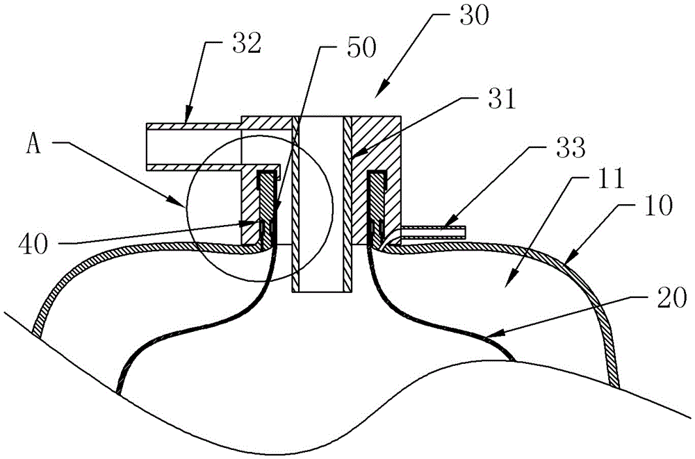
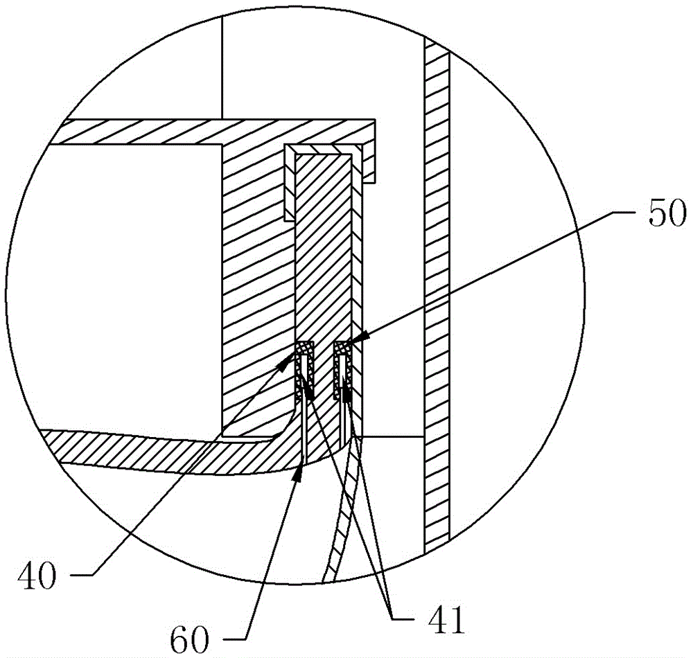
[0019] Embodiment 1 is basically as attached figure 1 and figure 2 Shown: a sealing structure of a pressure water storage device, including an outer shell 10, an elastic inner tank 20 and a pipe joint body 30, the elastic inner tank 20 is located in the outer shell 10, an air-filled cavity 11 is formed between the two, and the upper end of the outer shell 10 is provided with an opening , the upper end of the elastic liner 20 is provided with a water outlet, and the water outlet is located in the opening; the pipe joint body 30 is provided with a water inlet channel 31, a water outlet channel 32 and an inflation port 33, and the water inlet channel 31 and the water outlet channel 32 are all connected to the water outlet Connected, the pipe joint body 30 is connected to the upper end of the shell 10, and the elastic liner 20 is pressed on the upper end of the shell 10, the outer edge of the upper end of the shell 10 is provided with a first annular groove, and a first sealing r...

Embodiment 2

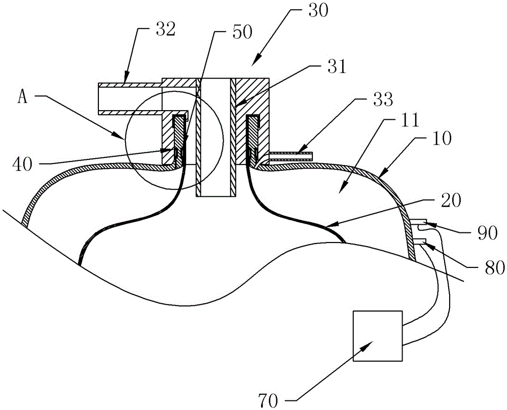
[0023] Such as image 3 As shown, the difference from Embodiment 1 is that this embodiment also includes a controller 70, an audible and visual alarm 80, and a pressure sensor 90 for detecting the pressure in the air chamber 11, and the pressure sensor 90 and the audible and visual alarm 80 Both are electrically connected to the controller 70 . The pressure sensor 90 can detect the pressure in the inflatable chamber 11 in real time. When the compressed gas in the inflatable chamber 11 leaks, when the water storage device drains, the pressure of the drain becomes smaller, thereby causing the drainage process to be affected; in the same state (such as water injection) completion or after the drainage is completed), the pressure sensor 90 detects that the pressure in the inflatable cavity 11 becomes smaller, and then transmits the signal to the controller 70, and the controller 70 controls the external inflatable device to inflate the inflatable port 33 to ensure water storage n...


PUM


Abstract

The invention discloses a pressure water-storage device sealing structure. The pressure water-storage device sealing structure comprises an outer shell, an elastic liner and a pipe joint. The elastic liner is located in the outer shell, an aeration cavity is formed between the elastic liner and the outer shell, and a water outlet is located in an opening; the pipe joint is provided with a water inlet channel, a water outlet channel and an aeration opening; the water inlet channel and the water outlet channel are both communicated with the water outlet; the pipe joint is connected with the upper end of the outer shell, and the elastic liner is compressed to the upper end of the outer shell; a first annular groove is formed in the outer edge of the upper end of the outer shell, and a first seal ring is disposed in the first annular groove; a second annular groove is formed in the inner wall of the opening of the outer shell, and a second seal ring is disposed in the second annular groove; expansion chambers are formed in both the first seal ring and the second seal ring; air inlet holes communicated with the expansion chambers are formed in the first seal ring and the second seal ring; air channels communicated with the air inlet holes of the first seal ring and the second seal ring are formed in the outer shell. By means of the pressure water-storage device sealing structure, a pressure water-storage device is good in airtightness, and leakage of compressed gas in the aeration cavity can be prevented.

Description

technical field [0001] The invention relates to a general pressure vessel, in particular to a sealing structure of a pressure water storage device. Background technique [0002] The pressure water storage tank has been widely used in water treatment systems, such as water purification products. It is equipped with an elastic inner liner material. After the water is pressurized, it can be stored in the elastic inner tank through the water inlet and outlet ports. The more water is injected, the elastic inner tank will continue to expand, the outer air will be continuously compressed, and the pressure will continue to rise after the air is compressed. The pressure on the side will reach equilibrium, and the water filling process will be completed. When water needs to be used, once the water outlet channel is opened, the external water pressure is lower than the internal pressure of the leather bag, and the water will be automatically delivered to the outside of the water stora...

Claims


Application Information

Patent Timeline
IPC IPC(8): F16J15/48
CPCF16J15/48
Inventor 朱立武
Owner 重庆杰鑫直饮水净化设备有限公司
Features
  • Generate Ideas
  • Intellectual Property
  • Life Sciences
  • Materials
  • Tech Scout
  • Unparalleled Data Quality
  • Higher Quality Content
  • 60% Fewer Hallucinations
Learn More