One-way conduction fluid sensor

A fluid sensor, one-way conduction technology, applied in the field of sensors, can solve the problems of water leakage in the casing, large resistance of the partition, and enlarged gap, and achieve the effect of preventing reverse flow, low production cost, and small fluid resistance.

Active Publication Date: 2016-03-23
因而克智能科技(浙江)有限公司
View PDF8 Cites 6 Cited by
  • Summary
  • Abstract
  • Description
  • Claims
  • Application Information

AI Technical Summary

Problems solved by technology

[0002] CN103411019A discloses "A Water Flow Sensor", which includes a housing, a float, a magnet, a return spring and a magnetic switch. The magnet is arranged on the float; the magnetic switch is arranged on the housing; There is a water guide chamber, the two ends of the water guide chamber are connected with the threaded interface; the water guide chamber has a through hole through the shell wall; it also includes a cylinder with a lower opening, and the float is set in the cylinder, and the lower end of the return spring and the upper end of the float The upper end of the abutment and the top plate of the cylinder are matched, and the cylinder and the shell are fixedly connected together by bolts; the lower opening of the cylinder is opposite to the through hole, and the lower end of the float is attached to the through hole and the partition when there is no water flow through; When there is water flow through, the float moves upward, and the water flows over the partition to the other side of the partition. Its disadvantages are: first, there is no limiter for the upward movement of the float, and repeated pressing of the spring for a long time will cause the spring to lose easily. The second is that the cylinder and the shell are connected by bolts, which may easily cause the shell to leak; the third is the sliding connection between the float and the cylinder. Due to factors such as machining accuracy and friction, the gap between the float and the cylinder will increase. Large, high-pressure water will flow from the gap to the spring chamber on the upper side of the float, making it difficult for the float to move up or not in place, resulting in the magnetic switch not working properly; Fourth, the resistance of the diaphragm to the water is large, which directly affects the power of the water body; The structure of the fluid sensor is complicated, the processing is difficult, the failure rate is high, and the maintenance cost is high

Method used


Image

  • One-way conduction fluid sensor
  • One-way conduction fluid sensor

Examples


Embodiment Construction

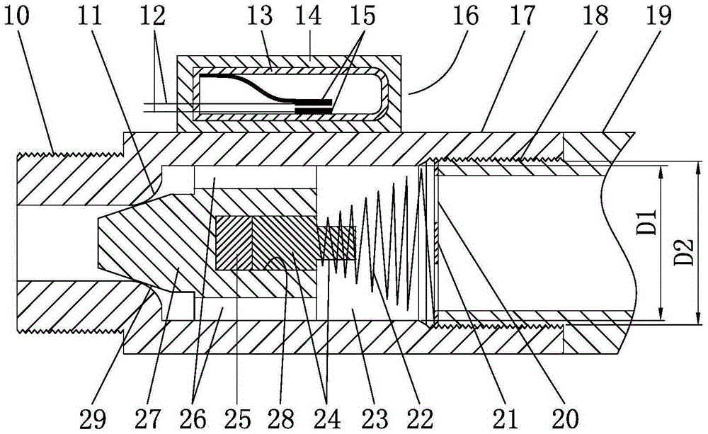
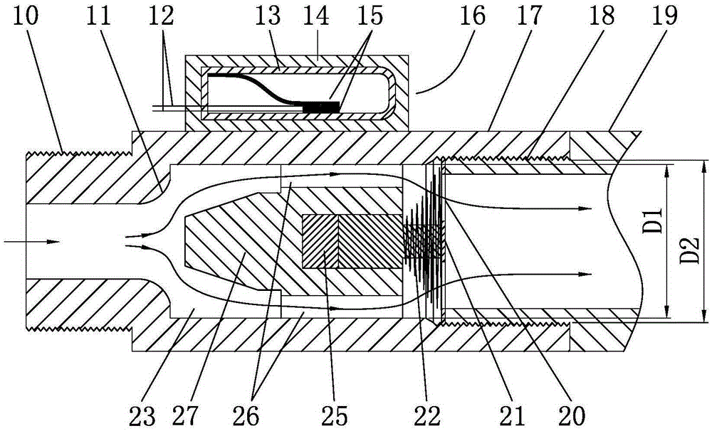
[0023] Below in conjunction with accompanying drawing, the present invention will be further described with specific embodiment, see figure 1 — figure 2 :

[0024] A kind of one-way conduction fluid sensor, a valve seat 11 is provided on the inner wall of one end of the housing 17 with a fluid channel, and a valve core 27 embedded with a magnetic block 25 and controlling forward conduction and reverse cut-off is provided on the valve seat 11, The tail of the valve core 27 is provided with a limit rod 24, the tail end of the limit rod 24 points to the other end of the housing 17, and the inner wall of the other end of the housing 17 is provided with a limit spring seat 21 with a fluid through hole 20, One side of the return spring 22 is sleeved on the limit rod 24, and the other side is connected to the limit spring seat 21. The outer wall of the housing 17 is provided with a valve core 27 that is opened or closed by the magnetic force of the magnetic block 25. Closed magnet...


PUM


Abstract

The invention belongs to the technical field of sensors and relates to a one-way conduction fluid sensor. The one-way conduction fluid sensor is characterized in that a valve seat is arranged on the inner wall of one end of a housing with a fluid channel; a valve element inlaid with a magnet block and being capable of controlling positive conduction and reverse blocking is arranged on the valve seat; a limiting rod is arranged at the tail part of the valve element; the tail end of the limiting rod points to the other end of the housing; a limiting spring seat with a fluid through hole is arranged on the inner wall of the other end of the housing; one side of a reset spring is connected to the limiting rod in a sleeving manner; the other side of the reset spring is propped against and connected to the limiting spring seat; a magnetic switch which is turned on or off by virtue of magnetic force of the magnet block when the valve element is opened or closed is arranged on the outer wall of the housing. The one-way conduction fluid sensor has the advantages as follows: the structure is simple, the manufacture cost is low, the fluid resistance is small, the leakproofness is good, the service life is long, the using performance is stable and the sensor is applicable to high voltage or ultrahigh pressure and capable of controlling fluid flowing unidirectionally.

Description

technical field [0001] The invention belongs to the technical field of sensors, in particular to a unidirectional conduction fluid sensor. Background technique [0002] CN103411019A discloses "A Water Flow Sensor", which includes a housing, a float, a magnet, a return spring and a magnetic switch. The magnet is arranged on the float; the magnetic switch is arranged on the housing; There is a water guide chamber, the two ends of the water guide chamber are connected with the threaded interface; the water guide chamber has a through hole through the shell wall; it also includes a cylinder with a lower opening, and the float is set in the cylinder, and the lower end of the return spring and the upper end of the float The upper end of the abutment and the top plate of the cylinder are matched, and the cylinder and the shell are fixedly connected together by bolts; the lower opening of the cylinder is opposite to the through hole, and the lower end of the float is attached to the...

Claims


Application Information

Patent Timeline
Patent Type & Authority Applications(China)
IPC IPC(8): F16K15/02F16K27/02F16K37/00
CPCF16K15/025F16K27/0209F16K37/0025
Inventor 郑辉
Owner 因而克智能科技(浙江)有限公司
Why Eureka
Try Eureka