Electric heating system with continuously adjustable power and control method of electric heating system

A heating system and electric heating technology, applied in the direction of heating methods, electric heating devices, lighting and heating equipment, etc., can solve the problems of large pressure difference in the heat pump system and non-adjustable electric heating power, so as to increase the input power and reduce the input power , the effect of reducing the input power

Active Publication Date: 2016-03-23
四川长虹空调有限公司
View PDF7 Cites 18 Cited by
  • Summary
  • Abstract
  • Description
  • Claims
  • Application Information

AI Technical Summary

Problems solved by technology

When heating, when the temperature of the indoor coil or the air inlet of the air conditioner is lower than a certain value, the electric heating is turned on, and when it reaches a certain value, the electric heating is turned off, that is, the power of the electric heating cannot be adjusted
However, there are problems: due to the vast territory of our country, the temperature difference between day and night is large; at the same time, because the heat pump system and electric heating are turned on, the indoor temperature will gradually rise. As the outdoor temperature drops, the indoor temperature rises, and the pressure difference of the heat pump system becomes larger. The capacity gradually decreases, and the final increase or maintenance at room temperature mainly depends on the input of electric heating. However, due to the superposition of temperature at this time, it is easy to achieve the protection and withdrawal of electric heating conditions. Trigger protection to increase or maintain indoor temperature

Method used


Image

  • Electric heating system with continuously adjustable power and control method of electric heating system
  • Electric heating system with continuously adjustable power and control method of electric heating system
  • Electric heating system with continuously adjustable power and control method of electric heating system

Examples


Embodiment 1

[0059] In this example, an air-conditioning system is taken as an example to specifically illustrate the content of the present invention.

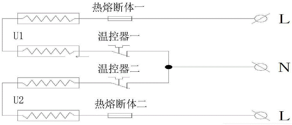
[0060] First of all, in order to increase the heat dissipation area and facilitate installation, the electric heating used in the air conditioner of this example adopts a U-shaped structure. The specific structure is as figure 1 As shown, it includes thermal fuse 1, U-shaped heating pipe U1, thermostat 1, thermal fuse 2, U-shaped heating pipe 2 U2, and thermostat 2. One end of the thermal fuse 1 is connected to the AC power supply The live wire end is connected, the other end of thermal fuse one is connected with one end of U-shaped heating pipe one, the other end of U-shaped heating pipe U1 is connected with one end of thermostat one, and the other end of thermostat one is connected with thermostat one. One end of the two is connected to the zero line end of the AC power supply, the other end of the thermostat two is connected to one en...

Embodiment 2

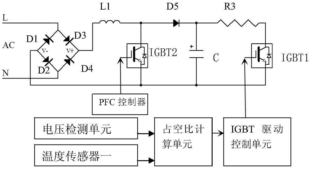
[0065]On the basis of Embodiment 1, in order to further ensure the accuracy of real-time duty cycle calculation, this example also includes a temperature sensor one, which is connected to the duty cycle calculation unit; the temperature sensor one is used to detect The real-time temperature of the electric heating circuit is transmitted to the duty cycle calculation unit; the duty cycle calculation unit is used to calculate the real-time temperature difference according to the real-time temperature of the electric heating circuit and the target temperature, and combine the real-time input voltage value and the real-time temperature difference according to the real-time temperature difference and The real-time duty ratio is calculated from the real-time power difference, and the real-time duty ratio is proportional to the real-time temperature difference and the real-time power difference; the duty ratio modulation circuit is used to modulate the output power of the power module ...

Embodiment 3

[0070] This example is based on the first and second examples, and solves the problem that the heating element of the air conditioner is easily deformed when the temperature is too high.

[0071] In order to solve the above problems, this example also includes a temperature sensor two, which is connected to the duty cycle calculation unit; the temperature sensor two is used to detect the temperature of the electric heating circuit and transmit it to the duty cycle calculation unit unit; the duty ratio calculation unit is used to compare the temperature of the electric heating circuit with the preset upper limit of the temperature of the electric heating circuit, when the temperature of the electric heating circuit is higher than the preset upper limit of the temperature of the electric heating circuit, The system reduces the current system operating duty cycle value according to the preset reduction amplitude; it is also used to compare the temperature of the electric heating c...


PUM


Abstract

The invention relates to an electric heating device and provides an electric heating control method with continuously adjustable power. The method comprises the following steps: firstly, a system receives a target temperature input by a user and calculates target power according to the target temperature, and the target temperature is in direct proportion to the target power; then the system detects real-time input voltage value, calculates the real-time power difference according to the real-time input voltage value and the target power and calculates the real-time duty cycle according to the real-time power difference, and the real-time power difference is in direct proportion to the real-time duty cycle; finally, the system modulates the output power of a power module according to the real-time duty cycle. The power output of the heating device is adjusted in real time according to the difference change of the current temperature and the target temperature, so that the effects of improving the heating comfort, improving the energy efficiency of an air conditioner, prolonging the service life of the product and reducing the energy consumption are realized, and the method is applicable to air conditioners, electric heaters and electric blankets.

Description

technical field [0001] The invention relates to an electric heating device, in particular to an electric heating device with continuously adjustable power. Background technique [0002] At present, in electrical products such as heating and cooling air conditioners and electric heaters, there are different forms of electric heating as the main or auxiliary heating appliances. Heating can be achieved by heat pump air conditioners, electric heaters directly, or both. Among them, electric heating is generally based on whether it is turned on or not. Taking the work of an air-conditioning heat pump as an example, for example, a 1000W electric heating has two states of on or off, and the electric heating is protected by a mechanical thermostat and a fuse. The air outlet structure of the air conditioner is generally made of plastic parts. Since the air conditioner heat pump itself has a large heating capacity output, as the indoor temperature rises, the temperature of the air outl...

Claims


Application Information

Patent Timeline
Patent Type & Authority Applications(China)
IPC IPC(8): F24F13/00H05B1/02
CPCF24F13/00H05B1/028
Inventor 李越峰高向军邓平
Owner 四川长虹空调有限公司
Why Eureka
Try Eureka