Ice maker and refrigerator

A technology for ice machines and ice trays, which is applied in ice making, ice making, household refrigeration devices, etc. It can solve problems such as unsatisfactory use requirements, reduced utilization of cold air, and reduced air volume of ice trays, so as to improve ice production. Effect, efficiency improvement, effect of shortening ice making cycle

Active Publication Date: 2018-05-11
HEFEI HUALING CO LTD +1
View PDF5 Cites 0 Cited by
  • Summary
  • Abstract
  • Description
  • Claims
  • Application Information

AI Technical Summary

Problems solved by technology

[0005] The technical problem to be solved by the present invention is: in order to solve the problem that there are many obstacles between the air inlet of the existing ice maker and the ice-making tray, this will form wind resistance, resulting in a decrease in the overall air volume supplied to the ice-making tray, and the use of cold wind The rate is greatly reduced, which makes the water in the ice-making tray slow down to form ice cubes, and the ice-making efficiency is low, which cannot meet the needs of use.

Method used


Image

  • Ice maker and refrigerator
  • Ice maker and refrigerator
  • Ice maker and refrigerator

Examples


Embodiment 1

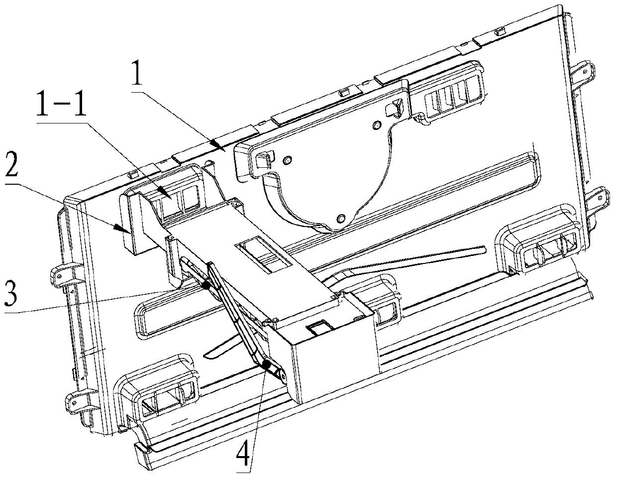
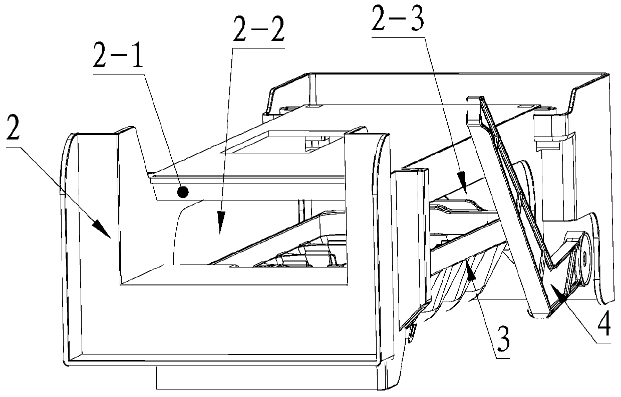
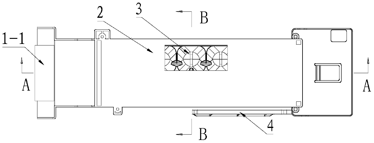
[0028] Such as Figure 2-5 As shown, the present invention discloses an ice maker, comprising: a bracket 2, an ice-making tray 3 and an ice-discharging motor 5, the ice-discharging motor 5 is installed on the bracket 2, and one end of the ice-making tray 3 It is driven and connected with the ice-discharging motor 5 to realize ice-discharging; the inside of the support 2 is provided with a cavity, the ice-making tray 3 is located in the cavity, and the side walls of the support 2 are respectively provided with the An air inlet connected to the cavity and at least one air outlet, the air inlet is used to guide cold air through the upper surface of the ice-making tray 3, from the inlet of the air inlet to the ice-making tray 3, the flow direction of the cold air in the horizontal direction remains unchanged. Preferably, the ice-making tray 3 is located in the extension direction of the air inlet, and the cold air blows directly to the ice-making tray 3 after coming out from the ...

Embodiment 2

[0039] This embodiment discloses a refrigerator, including a storage room, the storage room is provided with an air duct cover plate 1, and the air duct cover plate 1 is installed with the ice maker as described in the first embodiment; the bracket 2 and The air duct cover plate 1 is connected, and the air duct cover plate 1 is provided with an air port 1-1 communicating with the air inlet, and the air port 1-1 is used to connect the air duct cover plate 1 to another The cold air from the side passes into the air inlet. After the cold air in the refrigerator reaches the other side of the air duct partition, it enters the storage room through the air outlet 1-1 to realize cooling; after the ice machine is installed on the air duct cover plate 1, the cold air from the air outlet 1-1 directly enters the The wind is placed to realize ice making, and the cold air flowing out of the ice machine enters the storage room to realize the cooling of the refrigerator room.

[0040] prefer...


PUM


Abstract

The invention belongs to the technical field of refrigerator ice making, and discloses an ice maker and a refrigerator. The ice maker comprises a bracket, ice making cells and an ice discharge motor; the ice discharge motor is mounted on the bracket; the ice making cells are in drive connection with the ice discharge motor; a cavity is formed in the bracket; the ice making cells are positioned in the cavity; an air inlet and at least one air outlet are formed in the side wall of the bracket; and the air inlet is used for leading cold air to pass through the upper surfaces of the ice making cells. Compared with the prior art, the ice maker has the following prominent improvements: (1) more ice blocks can be made under the same conditions, so that the ice making quantity in unit time is large; (2) the frost blockage condition cannot be generated under the same conditions; and (3) the ice making cost is lower under the same ice making technical scheme conditions.

Description

technical field [0001] The invention relates to the technical field of refrigerator ice making, in particular to an ice maker and a refrigerator. Background technique [0002] The existing Chinese patent 201120468430.8 discloses an ice maker for a refrigerator. The ice maker includes a hanger, a drive motor, an ice probe, an ice tray, and an air duct formed by a cavity in the hanger. Wherein the air duct is provided with an air inlet and an air outlet, and is also provided with a baffle for guiding the cold air to the ice-making tray. The cold air enters the air duct from the air inlet, and is guided by the baffle and blows from the air outlet to the ice tray. [0003] In this scheme, the cold air needs to pass through the air inlet, the air duct, the baffle, and the air outlet to blow to the ice tray, especially the setting of the baffle, so that there are many obstacles between the air inlet and the ice tray. This will form wind resistance, reduce the overall air volume ...

Claims


Application Information

Patent Timeline
Patent Type & Authority Patents(China)
IPC IPC(8): F25D23/12F25C1/04
CPCF25C1/04F25D23/12
Inventor 邵阳金湘彧吕正光
Owner HEFEI HUALING CO LTD
Why Eureka
Try Eureka