Deformation monitoring coordinate reference establishment method and device based on three dimensional laser scanning

A deformation monitoring and three-dimensional laser technology, applied in the field of three-dimensional laser scanning, can solve problems such as efficiency limitation and loss of measurement accuracy, and achieve the effect of improving accuracy, simplifying operation methods, and reducing personal safety.

Active Publication Date: 2016-03-23
AVIC GEOTECHN ENG INST
View PDF5 Cites 17 Cited by
  • Summary
  • Abstract
  • Description
  • Claims
  • Application Information

AI Technical Summary

Problems solved by technology

[0006] At present, 3D laser scanning needs to set up "targets" in the deformation monitoring work, and needs to use total station or satellite positioning measurement equipment to measure the geodetic coordinate system, and at the same time establish the conversion relationship between the 3D laser scanning coordinate system and the geodetic coordinate system. This leads to a loss of measurement accuracy and limited efficiency, and deformation monitoring requires a stable and unchanging coordinate reference to calculate the amount of deformation

Method used


Image

  • Deformation monitoring coordinate reference establishment method and device based on three dimensional laser scanning
  • Deformation monitoring coordinate reference establishment method and device based on three dimensional laser scanning
  • Deformation monitoring coordinate reference establishment method and device based on three dimensional laser scanning

Examples


Embodiment Construction

[0034] Embodiments of the present invention are described in detail below, and examples of the embodiments are shown in the drawings, wherein the same or similar reference numerals denote the same or similar elements or elements having the same or similar functions throughout. The embodiments described below by referring to the figures are exemplary and are intended to explain the present invention and should not be construed as limiting the present invention.

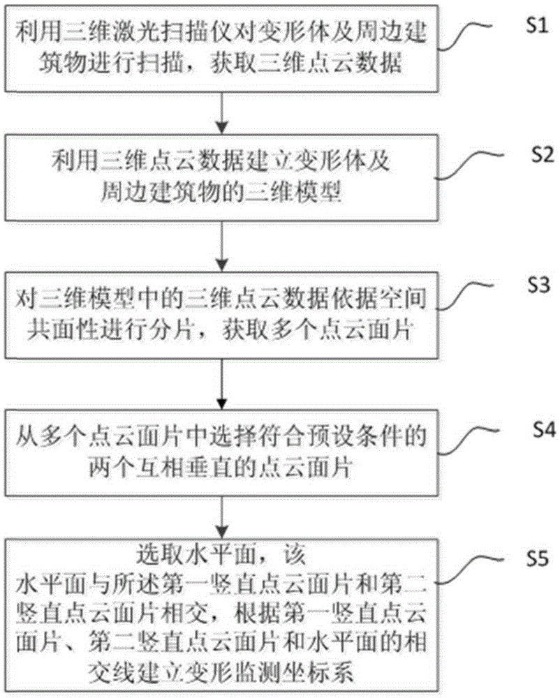
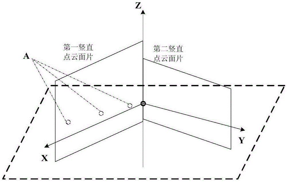
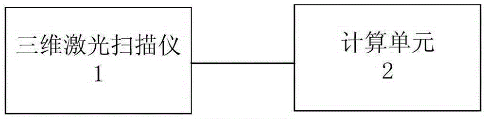
[0035] Since the coordinate system that the laser scanner relies on for each scanning data is independent, it is necessary to compare the coordinates of the deformed body in the same coordinate system in the deformation monitoring process to obtain whether the deformed body is deformed. The invention proposes a method and device for establishing a deformation monitoring coordinate system based on three-dimensional laser scanning, which are used to establish a unified coordinate system to calculate the deformation amount...


PUM


Abstract

The invention provides a deformation monitoring coordinate reference establishment method and device based on three dimensional laser scanning. The method comprises: utilizing a three dimensional laser scanner to scan a deformable body and surrounding buildings to acquire the three dimensional point cloud data; utilizing the three dimensional point cloud data to establish three dimensional models for the deformable body and the surrounding buildings; fragmenting the three dimensional point cloud data in the three dimensional models according to the space coplanarity to acquire a plurality of point cloud plane fragments; selecting two point cloud plane fragments which are mutually perpendicular to each other and accord with the preset condition among the plurality of point cloud plane fragments; selecting a horizontal plane, wherein the horizontal plane is intersected with the first vertical point cloud plane fragment and the second point cloud plane fragment; and according to the intersecting lines between the first vertical point cloud plane fragment and the second point cloud plane fragment and the horizontal plane, establishing a deformation monitoring coordinate system. The deformation monitoring coordinate reference establishment method can measure the three dimensional point cloud data of the deformable body through the three dimensional laser scanner, and then can establish a unified and stable deformation monitoring coordinate system as the monitoring reference so as to guarantee that the deformation measurement data through subsequent calculation is accurate and reliable.

Description

technical field [0001] The invention relates to the technical field of three-dimensional laser scanning, in particular to a method and device for establishing a deformation monitoring coordinate reference based on three-dimensional laser scanning. Background technique [0002] With the ever-changing pace of urban construction, high-rise buildings, large bridges, and foundation pit projects have developed rapidly. In the process of construction and operation, accurately obtaining the deformation value of the subject matter is an important means to ensure safety and conduct safety assessment, and how to efficiently and accurately measure the deformation value has always been the direction of efforts of surveyors and mappers. [0003] At present, three-dimensional laser scanning technology is mainly used in deformation monitoring. 3D laser scanning is a new measurement technology with the characteristics of fast speed, high precision, non-contact, and the ability to establish ...

Claims


Application Information

Patent Timeline
Patent Type & Authority Applications(China)
IPC IPC(8): G01B21/32
CPCG01B21/32
Inventor 李维功石俊成王永跃浦石薛德君李富荣付翔宇王笃礼
Owner AVIC GEOTECHN ENG INST
Why Eureka
Try Eureka