Light guide plate assembly, backlight and display device

A display device and light guide plate technology, which is applied in optical components, light guides, optics, etc., can solve the problems of thick backlight modules, general appearance quality, and large-size light guide plates that cannot be cut and screen-printed to achieve thinning Design, improve the appearance quality, and solve the effect that the screen printing cannot be cut

Active Publication Date: 2018-07-06
BOE TECH GRP CO LTD +1
View PDF5 Cites 0 Cited by
  • Summary
  • Abstract
  • Description
  • Claims
  • Application Information

AI Technical Summary

Problems solved by technology

[0002] For ultra-large liquid crystal display (≥82inch), the direct-type backlight design is usually used. This method does not require fine design such as screen printing, and can effectively improve the display effect and reliability of the product. However, due to the need to reserve a certain In order to achieve better picture quality, the thickness of the backlight module is thicker, and the appearance quality is average.
[0003] If the side-type backlight design is used, although the thickness of the backlight module can be reduced, there will be a problem that the large-size light guide plate cannot be cut and screen-printed

Method used


Image

  • Light guide plate assembly, backlight and display device
  • Light guide plate assembly, backlight and display device
  • Light guide plate assembly, backlight and display device

Examples


Embodiment Construction

[0025] In order for those skilled in the art to better understand the technical solution of the present invention, the light guide plate assembly, backlight source and display device provided by the present invention will be described in detail below with reference to the accompanying drawings.

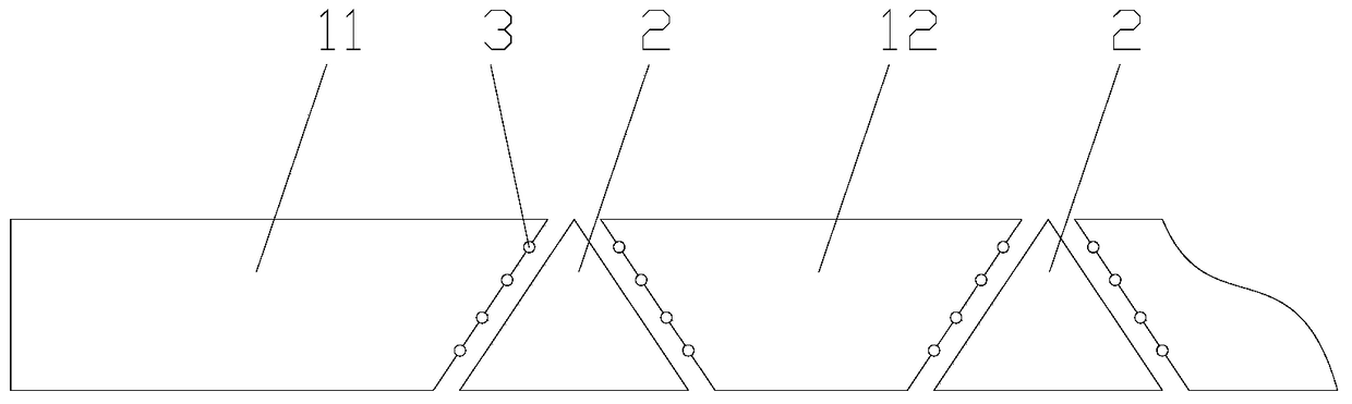
[0026] figure 1 A partial schematic diagram of the light guide plate assembly provided by the first embodiment of the present invention. see figure 1 , the light guide plate assembly includes N light guide plate splicing blocks and N-1 total reflection lenses, and N is an integer greater than 1, wherein, the N light guide plate splicing blocks are sequentially arranged at intervals along the light propagation direction. Among the N light guide plate splicing blocks, the projections of two light guide plate splicing blocks 11 respectively located at the near light end (the end close to the light source) and the far light end (the end far away from the light source) on a plane parallel...


PUM


Abstract

The invention provides a light guide plate assembly, a backlight source and a display apparatus. The light guide plate assembly comprises N light guide plate splicing blocks and N-1 total reflection lenses, wherein N is an integer greater than one, and the N light guide plate splicing blocks are successively arranged at intervals along the spreading direction of light; the N-1 total reflection lenses are spliced between gaps of every two adjacent light guide plate splicing blocks in a one-to-one corresponding manner so as to form a large-dimensional light guide plate and spread the light passing by in a lossless manner; and every two adjacent surfaces of the light guide plate splicing blocks and the total reflection lenses are provided with light change structures for damaging a total reflection phenomenon occurring on light-emitting surfaces of the light guide plate splicing blocks. The light guide plate assembly provided by the invention can realize a thin design of a large-dimension backlight source so as to improve the appearance quality of a display apparatus.

Description

technical field [0001] The invention relates to the manufacturing field of display devices, in particular to a light guide plate assembly, a backlight source and a display device. Background technique [0002] For ultra-large liquid crystal display (≥82inch), the direct-type backlight design is usually used. This method does not require fine design such as screen printing, and can effectively improve the display effect and reliability of the product. However, due to the need to reserve a certain The optical cavity is used to achieve better picture quality, resulting in a thicker backlight module and a mediocre appearance. [0003] If the side-type backlight design is adopted, although the thickness of the backlight module can be reduced, there will be a problem that the large-sized light guide plate cannot be cut and screen-printed. Contents of the invention [0004] The present invention aims to solve at least one of the technical problems existing in the prior art, and ...

Claims


Application Information

Patent Timeline
IPC IPC(8): G02B6/00G02F1/13357
CPCG02B6/003G02B6/0031G02B6/004G02B6/0065G02F1/133615
Inventor 张宇贾丽丽周昊池海耿仕新
Owner BOE TECH GRP CO LTD
Why Eureka
Try Eureka