

Compensation filter device in multi-sequence laser shadow photography
A technology for compensating filter devices and laser shadows. It is applied to filters for photography, cameras, optics, etc. to improve imaging uniformity, achieve uniformity, and eliminate interference fringes.
- Summary
- Abstract
- Description
- Claims
- Application Information
AI Technical Summary
Problems solved by technology
Method used
Image

Examples
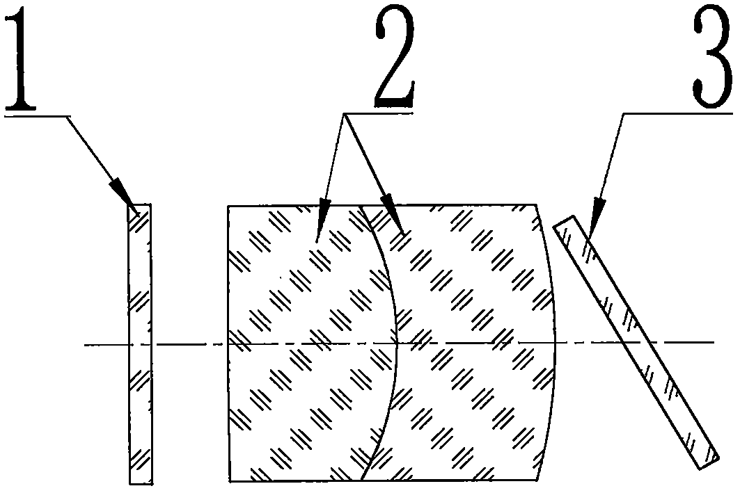
Embodiment 1
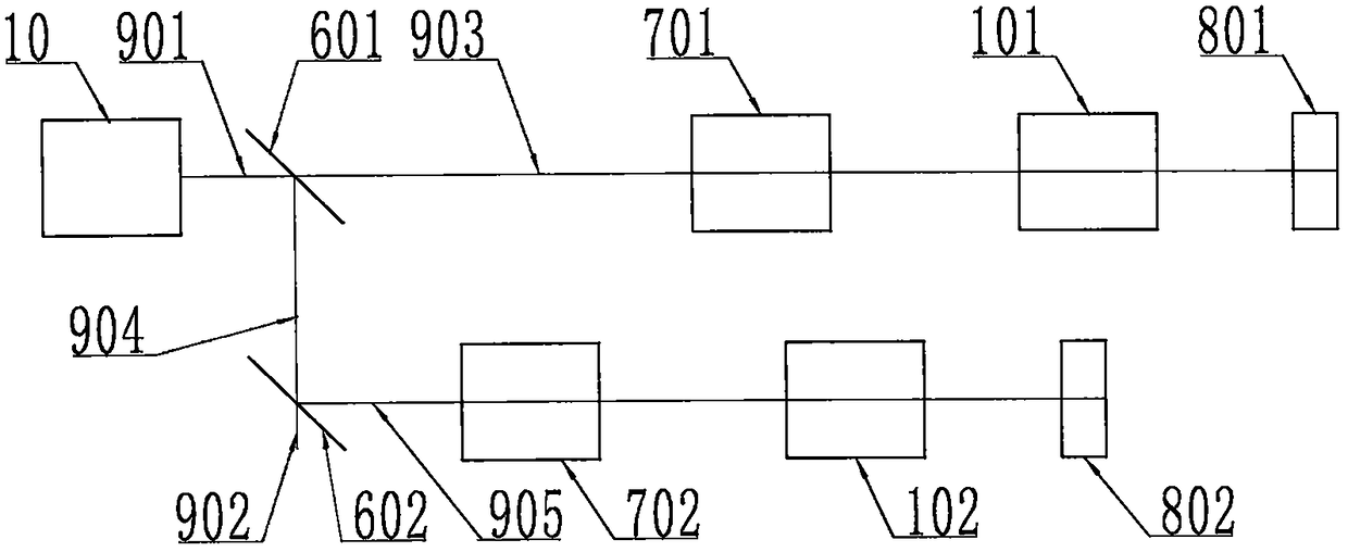
[0024] The layout of the compensation filter device in the sequential imaging optical path is as follows: image 3 As shown, the beam (901) coming out of the collimation system (10) in the multi-sequence laser shadow imaging is split into the first sequence beam (903) and the second sequence beam (904) by the first beam splitter (601) , first place the first collimating mirror (701) in the first sequence of light beams (903), and then place the first compensation filter device (101) and the first imaging CCD (801). The second sequence beam (904) is divided into the third sequence beam (905) and the fourth sequence beam (902) by the second beam splitter (902), and the second collimator is placed first in the third sequence beam (905). mirror (702), and then place the second compensation filter device (102) and the second imaging CCD (802).
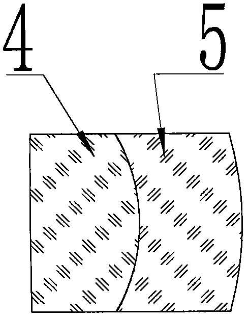
[0025] Wherein, the positions of the compensating filter devices in the other sequences of light beams are similar to those of the first ...
PUM
| Property | Measurement | Unit |
|---|---|---|
| thickness | aaaaa | aaaaa |
| thickness | aaaaa | aaaaa |
| radius | aaaaa | aaaaa |
Abstract
Description
Claims
Application Information