Optical imaging light source for detection

An optical imaging and light source technology, applied in the direction of light source, electric light source, point light source, etc., can solve the problems of single angle, poor heat dissipation effect, low power of LED light source, etc., to achieve low calorific value, high lighting intensity and stable lighting Effect

Active Publication Date: 2014-03-26
BEIJING BANKNOTE CURRENCY DESIGNING & PLATING +2
View PDF4 Cites 7 Cited by
  • Summary
  • Abstract
  • Description
  • Claims
  • Application Information

AI Technical Summary

Problems solved by technology

[0005] Aiming at the problems existing in the prior art such as low LED light source power, single angle, and poor heat dissipation effect, the present invention proposes a combination of hardware means and control means to solve the heating problem of the LED light source, which can support high-power LED light source stability Optical imaging light source for plate detection with long-time luminescence

Method used


Image

  • Optical imaging light source for detection

Examples


Embodiment Construction

[0026] The present invention will be described below in conjunction with the accompanying drawings.

[0027] In order to make the object, technical solution and advantages of the present invention clearer, the present invention will be further described in detail below in conjunction with the accompanying drawings and embodiments.

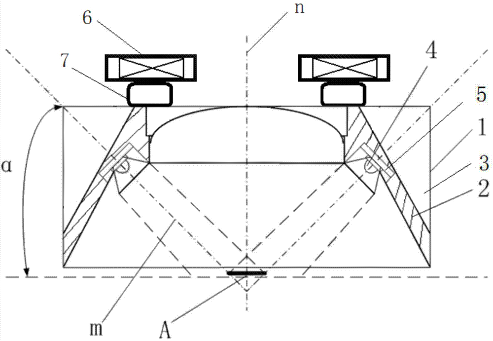
[0028] Such as figure 1 As shown, the optical imaging light source of the present invention includes a light box 1. The light box 1 includes an annular frame body 2 and a heat sink 3 extending outward from the outer wall of the annular frame body 2. The overall outline of the light box 1 is a cylinder. The annular frame body 2 is a hollow cylinder, rectangular cylinder or conical cylinder surrounded by the centerline n of the light box 1. The preferred annular frame body 2 of the present invention is a conical cylinder with a trapezoidal longitudinal section. The shape of each cooling fin 3 is a right triangle, the hypotenuse of the right triangle...


PUM


Abstract

The invention relates to an optical imaging light source for detection. The optical imaging light source comprises a light box composed of an annular frame body and cooling fins, and the annular frame body is in a barrel shape. The cooling fins are arranged on the outer side wall of the annular frame body, a plurality of LED light sources are arranged on the inner side wall of the annular frame body, the rated power of the LED light sources is higher than 1W, and the optical axes of the LED light sources can be focused behind a focal plane below the annular frame body. A plurality of fans are arranged at the top of the light box. When the temperature in the light box is higher than a safety threshold value, the fans are turned on. When the temperature in the light box is lower than the safety threshold value, the fans are turned off. The power of the LED light sources is adjusted through a power system, the work modes of the power system comprise a continuous mode and a trigger mode, and the trigger mode works in cooperation with a camera. Due to the fact that the LED light sources with the rated power higher than 1W are adopted, the illumination effect is better than that of other optical imaging light sources with low-power LED light sources. The heat quantity of the LED light sources is effectively controlled through the control means of hardware and control, the temperature of the light source is stabilized below the safety threshold value, and the service life of the optical imaging light source is effectively prolonged.

Description

technical field [0001] The invention relates to the field of printing plate detection, in particular to an optical imaging light source for detection. Background technique [0002] The quality of the original plate and printing plate of banknote glue gravure printing is the basis for ensuring the quality of printed products. Any quality problem in any of them will have a serious impact on the quality of printed products. At present, the detection of various printing plates is mainly carried out manually. The inspectors observe the surface of the printing plate by naked eyes, magnifying glass, local powdering, and scale measurement to confirm the quality of the plate. However, the effect of manual detection depends heavily on human experience, and the working hours are long and the efficiency is low. It is greatly affected by human subjective factors, and missed detections occur from time to time. [0003] In order to improve the degree of automation in plate inspection, aut...

Claims


Application Information

Patent Timeline
Patent Type & Authority Applications(China)
IPC IPC(8): F21S2/00F21V29/00G01N21/01F21Y101/02F21K9/00F21V29/67F21Y115/10
Inventor 刘永江杜旭东毕明张健冯礼卢继兵韩英魁常为民王雪
Owner BEIJING BANKNOTE CURRENCY DESIGNING & PLATING
Why Eureka
Try Eureka