
System for eliminating eye ground camera stray light

A stray light and camera technology, applied in ophthalmoscopes, eye testing equipment, medical science, etc., can solve problems such as complex calculations of the system

Inactive Publication Date: 2015-05-13
佛山市智海星空科技有限公司
View PDF5 Cites 7 Cited by
  • Summary
  • Abstract
  • Description
  • Claims
  • Application Information

AI Technical Summary

Problems solved by technology

[0005] In view of the deficiencies in the above-mentioned prior art, the purpose of the present invention is to provide users with a system for eliminating the stray light of the fundus camera, aiming at solving the problem of setting a black spot plate at a suitable position of the lighting system in the prior art to eliminate The backlight reflection of the eyepiece objective lens, the problem of complex calculation of the system

Method used


Image

  • System for eliminating eye ground camera stray light
  • System for eliminating eye ground camera stray light
  • System for eliminating eye ground camera stray light

Examples


Embodiment Construction

[0015] In order to make the object, technical solution and advantages of the present invention more clear and definite, the present invention will be further described in detail below with reference to the accompanying drawings and examples. It should be understood that the specific embodiments described here are only used to explain the present invention, not to limit the present invention.

[0016] See figure 2 , which is a schematic structural diagram of a preferred embodiment of the system for eliminating stray light in fundus cameras according to the present invention, wherein P is linearly polarized light whose vibration direction is parallel to the paper surface, and S is linearly polarized light whose vibration direction is perpendicular to the paper surface. The system for eliminating fundus camera stray light includes:

[0017] imaging subsystem and lighting subsystem;

[0018] The imaging subsystem consists of a 1 / 4 wave plate 110, an objective lens 120, a polariz...


PUM


Abstract

The invention provides a system for eliminating eye ground camera stray light. The system comprises an imaging subsystem and an illumination subsystem. The imaging system consists of a 1 / 4 wave plate, an eye objective lens, a polarized beam splitter prism and an imaging objective lens which are arranged in sequence. The illumination subsystem consists of an annular light source, a light uniformizing lens, a polarized beam splitter prism and an eye objective lens. After light emitted by the annular light source passes through the polarized beam splitter prism, linearly polarized light of vertical component is reflected, sequentially passes through the eye objective lens and the 1 / 4 wave plate and then enters the eyes of an observer, light reflected by the eye grounds of the eyes of the observer passes through the 1 / 4 wave plate and the eye objective lens and is transmitted into the imaging objective lens through the polarized beam splitter prism. After the polarized beam splitter prisms and the 1 / 4 wave plate are added into the system for eliminating the eye ground camera stray light, stray light of higher than 99.5%, produced by the eye objective lenses is eliminated, and stray light inhabitation effect is improved.

Description

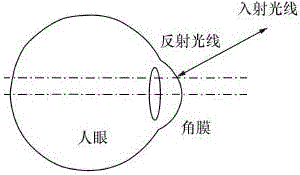
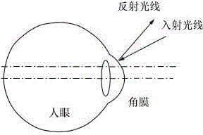
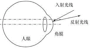
technical field [0001] The invention relates to the technical field of medical fundus imaging, in particular to a system for eliminating stray light from a fundus camera. Background technique [0002] Stray light refers to all abnormal light that enters the imaging system and affects the imaging quality. For the design of the fundus camera, the stray light mainly comes from the backlight reflection of the cornea of ​​the eye. Due to the high reflectivity of the cornea, the backlight reflection of the cornea will introduce a lot of stray light to the imaging system. If good suppression measures cannot be taken, the imaging light reflected by the retina will be lost in the stray light, seriously affecting the imaging system. image quality. As shown in Figures 1a-1c, they are schematic diagrams of the reflection of incident light from the first position, the second position, and the third position of the cornea. The first position of the cornea is the critical state of the in...

Claims


Application Information

Patent Timeline
IPC IPC(8): A61B3/15A61B3/12
Inventor 李丹
Owner 佛山市智海星空科技有限公司
Learn More