Distribution photometer

A spectrophotometer and light source technology, applied in photometry, optical radiation measurement, testing optical performance and other directions, can solve the problems of inconvenient alignment and positioning of the lamp under test, affecting the test accuracy, blocking signal light, etc. The effect of measuring, eliminating stray light, and improving measurement accuracy

Inactive Publication Date: 2007-10-24
HANGZHOU EVERFINE PHOTO E INFO
View PDF0 Cites 6 Cited by
  • Summary
  • Abstract
  • Description
  • Claims
  • Application Information

AI Technical Summary

Problems solved by technology

In order to eliminate stray light, in the darkroom (or dark box) of the goniophotometer test, a bucket-shaped light-absorbing cavity and a diaphragm are arranged on the front side of the optical receiver. Due to the rotation of the optical mirror, the opening of the diaphragm is required to be relatively large, so more The stray light will also be reflected to the light-receiving surface of the detector through the wall, the ground, the main body of the goniophotometer, etc., thereby affecting the test accuracy; The light-absorbing cavity needs a fixing device, which also partially blocks the signal light and affects the test accuracy
Alignment and positioning of the luminaire under test is also inconvenient

Method used


Image

  • Distribution photometer
  • Distribution photometer

Examples


Embodiment Construction

[0021] Below according to the embodiment of accompanying drawing, content of the present invention is described in further detail:

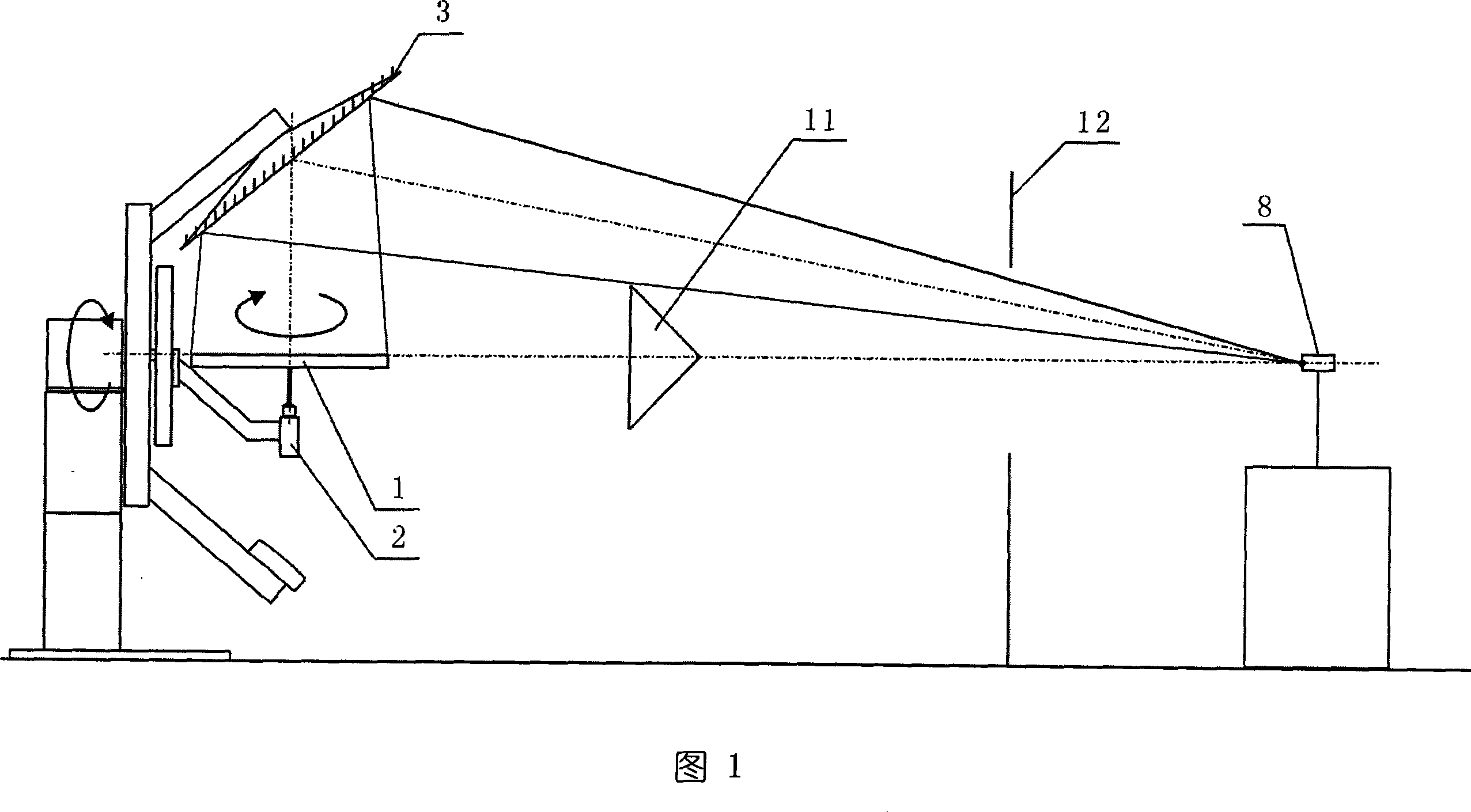
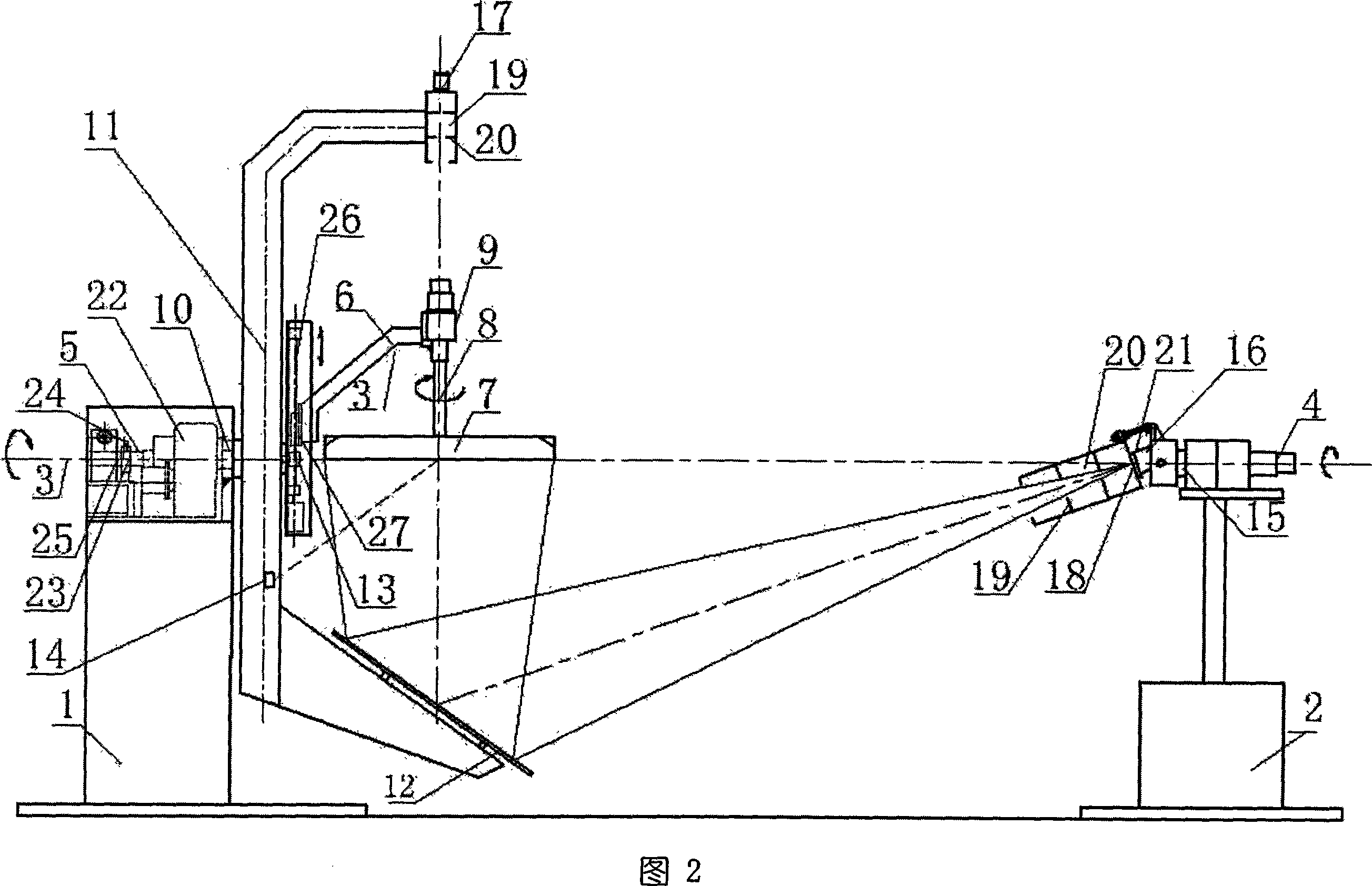
[0022]The synchronous reflectance goniophotometer as shown in Figure 2 includes two independent bases of the first base 1 and the second base 2, and the first rotation centerline 3 on the same horizontal line is respectively arranged on the two bases and the second centerline of rotation 4 . The first base 1 is provided with a hollow light source support shaft 5 whose center line coincides with the first rotation center line 3, and one end of the light source support shaft 5 coupled with the first base 1 is provided with an open circular hole 23 and Locking screw 24 constitutes a locking / releasing mechanism, and the light source support shaft 5 is sleeved in the hollow output shaft 25 of the worm gear; one end of the light source support shaft 5 is provided with a dovetail guide rail 26, and a slider 27 is arranged on the guide rail 26, and the s...


PUM


Abstract

The invention discloses a distribution photometer, comprising two independent bases, a mirror mounted one end of a pivoted arm connected with the first base, a first optical receiver mounted on another end of the pivoted arm, opposite an object light source, while the pivoted arm rotates the mirror and the first optical receiver around a first rotary central line, and a second optical receiver mounted on the second base, which rotates around the first rotary central line synchronously with the pivoted arm to synchronously receive the light beam reflected by the mirror, wherein the object light source via a lamp arm is connected with the first base, which rotates around itself shaft. The object light source is all in stable and natural burning point state, and the invention effectively reduces the measurement error via synchronously receiving the light beam of object light source to improve measurement accuracy, while the invention arranges two optical receivers to realize two measuring arm lengths without adjusting the mirror.

Description

【Technical field】 [0001] The invention relates to a photometric measuring instrument, which is mainly used for testing the light intensity distribution (or light distribution performance) in various directions of various indoor lamps, road lamps and flood lamps, and testing the total luminous flux of light sources and lamps. 【Background technique】 [0002] The existing circular motion mirror goniophotometer is shown in Figure 1. During the test, the light source to be tested is fixed on the test seat, so that the light source to be tested is rotated around the vertical axis. At the same time, the optical mirror is centered on the light source to be tested. Rotate around the horizontal axis, and use the detection device to receive the light reflected by the reflector, so as to measure the light distribution performance of the tested light source. [0003] The current circular motion mirror goniophotometer has the problem of troublesome adjustment of the measurement distance (...

Claims


Application Information

Patent Timeline
Patent Type & Authority Applications(China)
IPC IPC(8): G01J1/04G01M11/02
Inventor 潘建根
Owner HANGZHOU EVERFINE PHOTO E INFO
Why Eureka
Try Eureka