
Automatic calendar mechanism, movement and clock

A calendar and automatic technology, applied to clocks, mechanically driven clocks, and time-indicating mechanical devices, etc., can solve the problems of limited month and date display layout, complex structure, etc., and achieve the effect of simple composition and excellent degree of freedom

Active Publication Date: 2016-03-23
SEIKO INSTR INC
View PDF8 Cites 6 Cited by
  • Summary
  • Abstract
  • Description
  • Claims
  • Application Information

AI Technical Summary

Problems solved by technology

[0007] However, the prior art described in Patent Document 1 has a complicated structure because it has a planetary gear mechanism using a plurality of gears.
Moreover, in the prior art described in Non-Patent Document 1, since the month wheel and the date wheel are arranged coaxially, the display layout of the month and date is limited.

Method used


Image

  • Automatic calendar mechanism, movement and clock
  • Automatic calendar mechanism, movement and clock
  • Automatic calendar mechanism, movement and clock

Examples


Embodiment Construction

[0031] Hereinafter, embodiments of the present invention will be described with reference to the drawings.

[0032] Generally, the mechanical body including the driving part of a timepiece is called a "movement". The completed state of attaching the dial, hands, etc. to the movement and placing it in the case is called the "completion" of the timepiece. Of the two sides of the main plate constituting the timepiece substrate, the side with the glass of the case, that is, the side with the dial is referred to as the "back side" of the movement. And, the side with the case back cover of the watch case among the two sides of the main plate, that is, the side opposite to the dial is referred to as the “front side” of the movement.

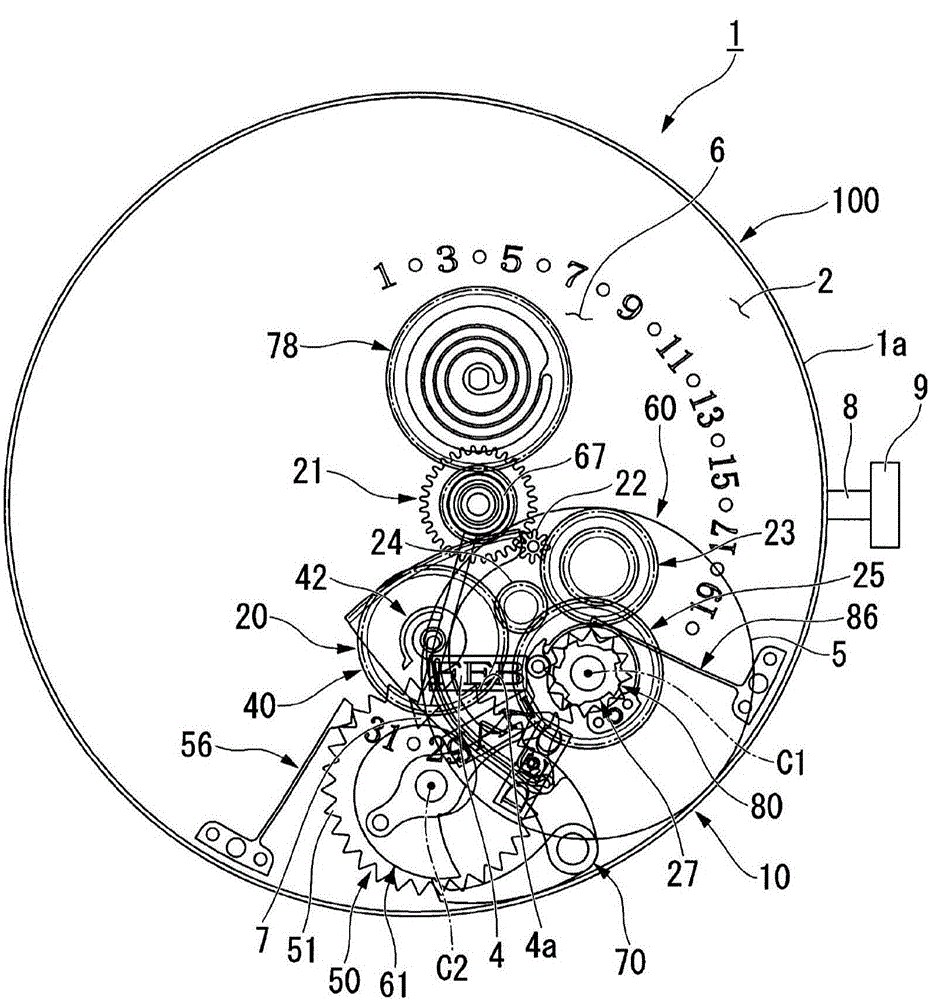
[0033] figure 1 It is a plan view of the timepiece 1, the movement 100 and the automatic calendar mechanism 10. in addition, figure 1 It is a plan view seen from the back side of the movement 100 . and, in figure 1 In , for convenience of descript...


PUM


Abstract

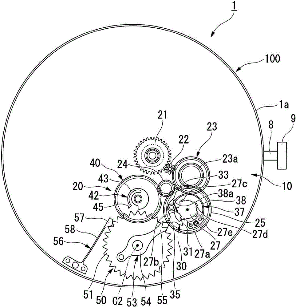
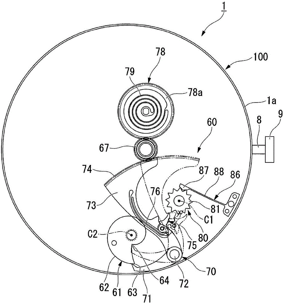
The invention provides an automatic calendar mechanism, a movement and a clock, wherein simple structure and high displaying freedom of month and date are realized. The automatic calendar mechanism (10) is provided with the components of a month wheel which rotates around a first shaft (C1) and rotates one circle in one year; a minor solar month date change wheel (25) which rotates around the first shaft (C1) and rotates one circle in one day; a minor solar month date feeding pawl (35) which is arranged on the minor solar month date change wheel (25) and performs displacement and synchronous rotation with the minor solar month date change wheel (25); a date changing wheel (40) which is provided with a date changing claw (42) and rotates one circle in one day; and a date wheel (50) which is provided with a month end claw (53) and a date wheel tooth part (51) that is pressed by the date changing claw (42), wherein the date wheel rotates around a second shaft (C2) and rotates a circle in one month. The minor solar moth date feeding pawl (35) presses a month end pawl (53) at a last day of a minor solar month in which the number of days is less than 30, thereby making a date wheel (50) rotate.

Description

technical field [0001] The invention relates to an automatic calendar mechanism, a movement and a clock. Background technique [0002] In clocks and watches with a calendar capable of displaying the month and day, such a calendar mechanism (hereinafter referred to as "automatic calendar mechanism") is known: by performing two-day calendar at the end of a small month in which the number of days in a month is 30 days or less. The amount of date is fed, and the date correction is suppressed to a minimum (for example, refer to Patent Document 1 and Non-Patent Document 1). [0003] In Patent Document 1, there is described an automatic calendar mechanism having a planetary gear mechanism having: a month satellite portion having five driving teeth; Has a direct drive relationship. [0004] Also, an automatic calendar mechanism is described in the non-patent literature, which has: a control cam; a month display swing arm operated by the control cam; a month display swing arm claw;...

Claims


Application Information

Patent Timeline
Patent Type & Authority Applications(China)
IPC IPC(8): G04B19/24G04B19/253
CPCG04B19/2538
Inventor 森裕一
Owner SEIKO INSTR INC
Learn More