Auxiliary positioning device and method for adjustable radar feed source

An auxiliary positioning and adjustable technology, which is applied in the direction of measuring devices, optical devices, and feedback control, etc., can solve the problem of inability to quantify the exact relationship between increasing or decreasing gaskets and the position of the feed source, the inability to obtain the feed source installation surface, and low efficiency And other issues

Active Publication Date: 2016-03-23
THE 724TH RES INST OF CHINA SHIPBUILDING IND
View PDF7 Cites 5 Cited by
  • Summary
  • Abstract
  • Description
  • Claims
  • Application Information

AI Technical Summary

Problems solved by technology

The adjustment process is mainly to adjust the position of the feed source at the end of the bracket by adding or subtracting spacers on the basis of the processed feed source support. This method has several disadvantages: First, it is impossible to quantify the position of the increase or decrease spacers and the feed

Method used


Image

  • Auxiliary positioning device and method for adjustable radar feed source
  • Auxiliary positioning device and method for adjustable radar feed source

Examples


Embodiment Construction

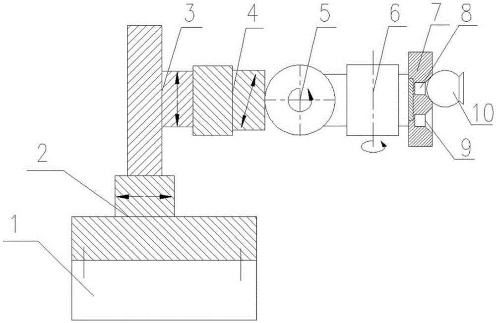
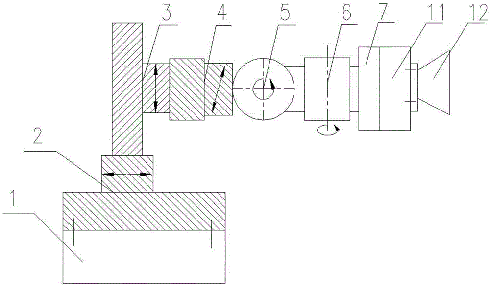
[0009] The invention relates to an adjustable radar feed source auxiliary positioning device and method. The specific implementation steps are as follows:

[0010] Step 1: When using the device to measure auxiliary positioning, first install the installation base 1 on the corresponding installation surface of the antenna system, and then adjust the positions of the guide rails 2, 3, 4 and the rotating shafts 5, 6 to the midpoint.

[0011] Step 2: Use the laser tracker to start establishing the benchmark of the antenna system, and import the theoretical 3D model, then the theoretical positions of the focus of the reflector and the phase center of the feed can be known. Among them, since the measurement and adjustment of the reflector is carried out before the phase center of the feed source, the coordinates of the focus of the reflector should be determined by the adjusted actual position.

[0012] Step 3: When it is necessary to measure the structural position, place the targ...


PUM


Abstract

The invention discloses an auxiliary positioning device and method for an adjustable radar feed source, and the device comprises an installation substrate, three guide rails with translational freedom degrees, and two rotating shafts with rotational freedom degrees. The installation substrate serves as a base, and the guide rails are mutually orthogonal in postures, thereby forming three translational freedom degrees. The housing of the lateral rotating shaft is installed on a sliding block on the guide rail at a tail stage, and the longitudinal rotating shaft is disposed on a step shaft on the lateral rotating shaft, and is perpendicular to the lateral rotating shaft, so as to form two orthogonal rotational freedom degrees. A fixed seat located at the tail end of the device can be directly used for target sphere measurement of a laser tracker or the electrical performance testing of a feed source through a feed source adapter board. When the device is used for measuring and adjusting the position of the feed source, the adjustment amounts of the plurality of freedom degrees can be directly read. The device can provide accurate data of the position of the feed source, and improves the efficiency of the positioning of the feed source.

Description

technical field [0001] The invention is an adjustable auxiliary positioning device used when the antenna feed source is positioned and measured during the assembly and debugging process of the radar antenna system. Background technique [0002] Before the post-assembly and debugging of the radar antenna system, the position of the feed source needs to be pre-positioned. Due to the complex structure of the antenna system, the phase center and the relative position of the focus between the feed source and the reflector are usually directly adjusted for measurement. At present, a reliable and efficient method is to use a laser tracker for high-precision position measurement, and continuously give the error between the actual coordinates of the feed source and the design coordinates until the feed source is adjusted to the allowable range of the error. The adjustment process is mainly to adjust the position of the feed source at the end of the bracket by adding or subtracting sp...

Claims


Application Information

Patent Timeline
IPC IPC(8): G05D3/12G01B11/00G01S7/02
CPCG01B11/00G01S7/02G05D3/12
Inventor 李珂翔王宏杰吴佳
Owner THE 724TH RES INST OF CHINA SHIPBUILDING IND
Why Eureka
Try Eureka