
Heavy type prefabricated grouting steel tube compound column and processing method

A technology of grouting steel pipes and processing methods, which is applied in the direction of columns, pier columns, pillars, etc., can solve the problems of poor welding construction conditions, potential safety hazards, and difficult quality assurance, so as to increase processing difficulty, reduce processing difficulty, and ensure The effect of machining accuracy

Active Publication Date: 2018-08-14
湖北绿筑装配科技有限公司
View PDF5 Cites 2 Cited by
  • Summary
  • Abstract
  • Description
  • Claims
  • Application Information

AI Technical Summary

Problems solved by technology

Existing installation structures such as Figure 10 As shown in , each prefabricated grouted steel pipe is connected by flanges. The problem is that the load-bearing columns of high-rise buildings may also need to bear lateral stress in addition to axial stress, and the flanges are connected by bolts. connection, weaker shear strength, weaker lateral forces, so usually need to be overcome by increasing the diameter
But this will take up more space in the building interior
[0003] Chinese patent document CN206158011U describes a semi-fabricated ultra-high-strength steel pipe grouting laminated column structure. This scheme adopts the method of on-site welding connection using ring-shaped connecting partitions, but the construction efficiency of this structure is low, especially, the on-site The welding construction conditions are poor, the quality after welding is difficult to guarantee, and potential safety hazards are prone to occur

Method used


Image

  • Heavy type prefabricated grouting steel tube compound column and processing method
  • Heavy type prefabricated grouting steel tube compound column and processing method
  • Heavy type prefabricated grouting steel tube compound column and processing method

Examples


Embodiment 2

[0055] A processing method for the above-mentioned heavy fabricated grouted steel pipe composite column, comprising the following steps:

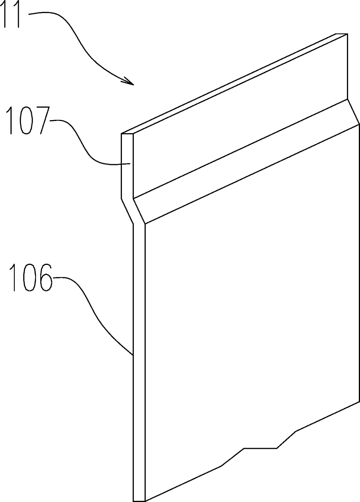
[0056] s1. Cutting the vertical board 12 and the seam repairing board 11; in this example, CNC wire cutting machine is used for cutting to ensure the dimensional accuracy.

[0057] s2, bending the vertical board 12 and the seam repairing board 11 according to the preset shape;

[0058] The preferred solution is as Figure 9 Among them, in this step, the riser 12 is heated to a predetermined temperature; the heating temperature is different according to different materials, and the heating temperature in this example is 900-1100 degrees Celsius.

[0059] The plate 100 to be processed, here the vertical plate 12 comes out of the heating furnace, and the vertical plate 12 is sent to the edge folding device 4 by the feeding trolley 41 for hemming; in a preferred solution, the feeding trolley 41 The top of the top is provided with roller table...


PUM


Abstract

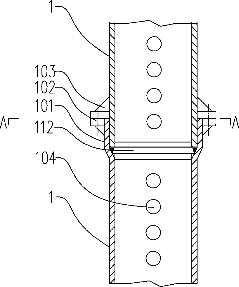
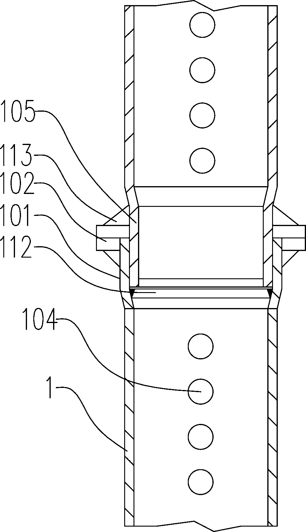
The invention provides a heavy type prefabricated grouting steel tube compound column and a processing method. An edge-extending end head is arranged at one end of a tubular column, and an edge-extending end head flange is arranged on the edge of the edge-extending end head. A cavity which comprises a plurality of side walls is formed in the edge-extending end head, the other end of the tubular column can be sleeved with the cavity, and an end head flange used for connecting the edge-extending end head flange is arranged on the side wall, close to the end head, of the other end of the tubularcolumn. A vertical plate and a seam-repairing plate are bent and formed according to a preset shape. The vertical plate, an edge-extending end head plate and the seam-repairing plate are connected andformed by an edge-extending end head welding die and a middle portion locating welding die. The edge-extending end head flange is welded. The heavy type prefabricated grouting steel tube compound column is obtained by the steps. The lateral stress strength of the heavy type prefabricated grouting steel tube compound column is dramatically improved by adopting a covering-closing structure and a combined structure of flange connection, under the same load bearing requirements, the size of the heavy type prefabricated grouting steel tube compound column can be reduced.

Description

technical field [0001] The invention relates to the field of grouted steel pipes used in high-rise buildings, in particular to a heavy-duty assembled grouted steel pipe laminated column and a processing method thereof. Background technique [0002] Existing high-rise buildings require load-bearing columns to have a higher load-bearing capacity, so a prefabricated column that can be grouted in the inner cavity and outer wall of the steel pipe has been developed, and the weight of a single heavy-duty fabricated grouted steel pipe can reach up to ten tons. Existing installation structures such as Figure 10 As shown in , each prefabricated grouted steel pipe is connected by flanges. The problem is that the load-bearing columns of high-rise buildings may also need to bear lateral stress in addition to axial stress, and the flanges are connected by bolts. The connection, the shear strength is weaker, and the lateral force is weaker, so it usually needs to be overcome by increasin...

Claims


Application Information

Patent Timeline
Patent Type & Authority Applications(China)
IPC IPC(8): E04C3/34B23P15/00
CPCB23P15/00E04C3/34
Inventor 宿贵兰
Owner 湖北绿筑装配科技有限公司
Learn More