Lathe clamp for machining blade dehumidification groove

A vehicle fixture and blade technology, applied in the direction of manufacturing tools, metal processing equipment, metal processing machinery parts, etc., can solve the problems of no fixture, the blade dehumidification tank cannot be processed, and the processing technology of the blade dehumidification tank is inconvenient, so as to improve production efficiency, Processing quality leaps to ensure the effect of processing and production requirements

Inactive Publication Date: 2018-01-12
HARBIN TURBINE
View PDF9 Cites 2 Cited by
  • Summary
  • Abstract
  • Description
  • Claims
  • Application Information

AI Technical Summary

Problems solved by technology

[0003] The purpose of the present invention is to solve the problem that there is no suitable fixture for the new processing method of the blade dehumidification tank, so that the blade dehumidification tank cannot be processed on a five-axis CNC lathe, which brings inconvenience to the new blade dehumidification tank processing technology

Method used


Image

  • Lathe clamp for machining blade dehumidification groove
  • Lathe clamp for machining blade dehumidification groove
  • Lathe clamp for machining blade dehumidification groove

Examples


specific Embodiment approach 1

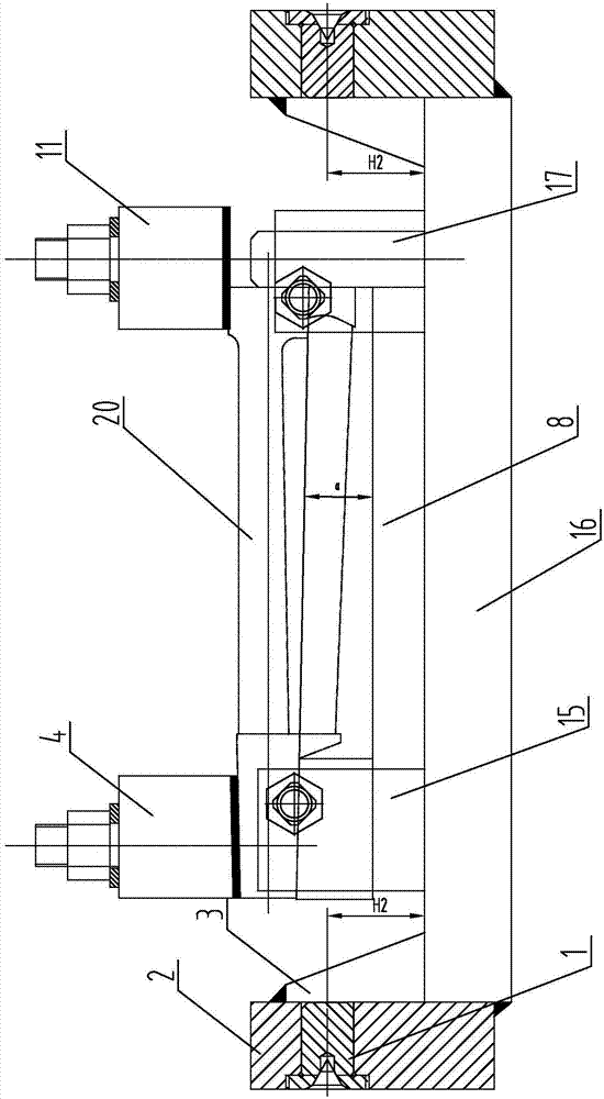
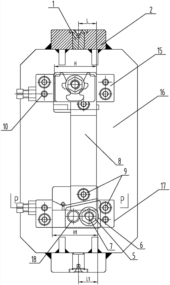
[0014] Specific implementation mode one: combine Figure 1 to Figure 6 Describe this embodiment. This embodiment includes a fixture main part, a positioning part and a clamping part. The blade 20 is installed on the fixture main part through the positioning part and the clamping part. The fixture main part includes two thimble seats 2 and two sets of ribs. The plate 3 and the bottom plate 16, the bottom plate 16 is a strip-shaped bottom plate, two thimble holders 2 are respectively installed on the two width directions of the bottom plate 16, and the joints of the two thimble holders 2 and the bottom plate 16 are respectively connected by a group of ribs 3 The positioning part includes the positioning part of the inner radial surface of the blade, the positioning part of the steam inlet edge of the blade root and the blade crown and the positioning part of the blade length direction, the positioning part of the inner radial surface of the blade is installed on the blade root po...

specific Embodiment approach 2

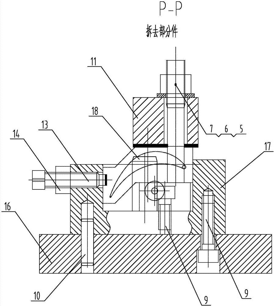
[0019] Specific implementation mode two: combination figure 2 and image 3 To illustrate this embodiment, the main part of the fixture in this embodiment also includes two thimble sleeves 1, each thimble base 2 is provided with a thimble sleeve installation hole, and each thimble sleeve installation hole is equipped with a thimble sleeve 1, and the thimble sleeve 1 There are thimble holes on the outside. In this way, the installation hole of the thimble sleeve is a stepped hole, which serves as the dehumidification rotation center. There are 2 purposes for the thimble sleeve to be designed as a stepped shape. One is to increase its rigidity to avoid deformation of the thimble positioning part of the fixture due to excessive clamping force when the lathe is clamped. The other is for the replaceability of the fixture. The thimble sleeve is an easy-wearing part. , The thimble hole is severely worn. In order to ensure the processing accuracy, the thimble sleeve is replaced reg...

specific Embodiment approach 3

[0020] Specific implementation mode three: combination figure 1 and image 3 Describe this embodiment, the blade inner radial surface positioning part of this embodiment includes the inner radial surface positioning block 8, the inner radial surface positioning block 8 is installed on the blade root positioning seat 15 and the blade shroud positioning seat 17, the inner radial surface positioning block 8 The radial angle matches the contact surface angle where the blades 20 meet. Such arrangement facilitates the positioning of the inner radial surface of the blade 20 . Other compositions and connections are the same as those in the second embodiment.

[0021] The radial angle of the positioning block 8 on the inner radial surface in this embodiment is α, and the value of α is consistent with the radial angle of the blade. The design in the width direction only needs to consider not interfering with the inner wing angle of the blade.


PUM


Abstract

The invention discloses a lathe clamp for machining a blade dehumidification groove, and relates to a clamp. The lathe clamp for machining the blade dehumidification groove aims to solve the problem that no appropriate clamp is provided aiming at a new blade dehumidification groove machining method at present, thus the blade dehumidification groove cannot be processed on a numerical control lathe,and inconvenience is brought to a new blade dehumidification groove machining technology. A blade is installed on a clamp body portion through a positioning portion and a clamping portion; two ejector pin seats are arranged in two width directions of a bottom plate respectively; the ejector pin seats are each connected with the base plate through a set of rib plates; a blade inner diameter direction surface positioning portion is installed on the bottom plate of the clamping portion of the clamp; a blade root leading edge positioning portion and a blade crown leading edge positioning portionare installed on the blade inner diameter direction surface positioning portion; the blade is positioned and installed on the blade crown leading edge positioning portion through a blade length direction positioning portion; a blade crown pressing plate and a blade root pressing plate are pressed and fitted on the blade. The lathe clamp for machining the blade dehumidification groove is used for machining the blade dehumidification groove.

Description

technical field [0001] The invention relates to a fixture, in particular to a vehicle fixture for processing blade dehumidification grooves. Background technique [0002] In the past, the blade dehumidification tank was milled by EDM and laser. The former has poor machining accuracy, while the latter has low finishing efficiency and high processing cost. Using a new processing method car dehumidification tank. In order to meet the new processing method of the process, it is necessary to provide corresponding fixture support. However, there is no suitable fixture for the new blade dehumidification groove processing method, so that the blade dehumidification groove cannot be processed on a five-axis CNC lathe to dehumidify the new blade. The groove machining process is inconvenient. Contents of the invention [0003] The purpose of the present invention is to solve the problem that there is no suitable fixture for the new processing method of the blade dehumidification ta...

Claims


Application Information

Patent Timeline
Patent Type & Authority Applications(China)
IPC IPC(8): B23Q3/12
Inventor 王玉君李铁成李变弟王海东黄兴军张宇航于志锋储继影
Owner HARBIN TURBINE
Why Eureka
Try Eureka