Method and device for determining lane line

A determination method and lane line technology, applied in the field of image processing, can solve the problems that are difficult to meet, do not consider occlusion and shadow, and the accuracy of lane positioning is limited.

Active Publication Date: 2016-03-23
BAIDU ONLINE NETWORK TECH (BEIJIBG) CO LTD
View PDF3 Cites 29 Cited by
  • Summary
  • Abstract
  • Description
  • Claims
  • Application Information

AI Technical Summary

Problems solved by technology

[0004] However, the accuracy of the lane positioning of the above two methods is limited by the shooting scene, that is, only by processing the scene with a large contrast between the lane line and the ro

Method used


Image

  • Method and device for determining lane line
  • Method and device for determining lane line
  • Method and device for determining lane line

Examples


Embodiment 1

[0030] Figure 1A It is a schematic flowchart of the method for determining lane lines provided in Embodiment 1 of the present invention, as shown in Figure 1A shown, including:

[0031] S11. Performing inverse projection transformation on the captured image;

[0032] Specifically, since the vehicle-mounted camera is placed parallel to the ground, the camera shoots along the forward direction of the vehicle. In this shooting angle, the lane lines show a form of narrower and narrower width from near to far, and are not parallel to each other, intersecting at the vanishing point at infinity. It is difficult to locate the lane line at this shooting angle. Therefore, it is first necessary to adjust the camera's viewing angle to be perpendicular to the ground through back projection.

[0033] For example, if the three-dimensional space coordinates corresponding to the camera are (X, Y, Z), the parameters of the camera are: focal length f x and f y , optical center coordinate c ...

Embodiment 2

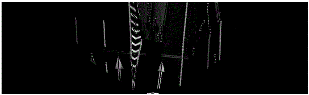
[0085] figure 2 A schematic structural diagram of a lane line determination device provided in Embodiment 2 of the present invention, as shown in figure 2 As shown, it specifically includes: an image transformation module 21, a rough extraction module 22, a first recognition module 23, a second recognition module 24 and a lane line determination module 25;

[0086] The image transformation module 21 is used to perform inverse projection transformation on the captured image;

[0087] The rough extraction module 22 is used to extract rough extracted image data including lane lines to be determined from the image data after back projection transformation;

[0088] The first recognition module 23 is used to input the roughly extracted image data into a first convolutional neural network model for recognition, and obtain a first recognition result of the to-be-determined lane line;

[0089] The second identification module 24 is used to perform inverse projection and inverse tr...


PUM


Abstract

The invention discloses a method and device for determining a lane line. The method comprises the following steps: performing inverse projection transformation on a photographed image; extracting rough extraction image data including a lane line to be determined from image data after inverse projection transformation; inputting the rough extraction image data into a first convolutional neural network model to recognize, and obtaining a first recognition result of the lane line to be determined; performing inverse projection transformation on the rough extraction image data, inputting the image data of the lane line to be determined after inverse transformation into a second convolutional neural network model to recognize, and obtaining a second recognition result of the lane line to be determined; and determining the lane line to be determined which satisfies a first preset condition as a true lane line according to the first recognition result and the second recognition result. The embodiment of the invention can accurately locate lane lines in the photographed images under various shooting scenes.

Description

technical field [0001] Embodiments of the present invention relate to the technical field of image processing, and in particular to a method and device for determining lane lines. Background technique [0002] With the rapid development of map navigation technology, map navigation technology has become an indispensable tool for people's daily travel. In map navigation, car navigation (including self-driving navigation and driverless navigation) has become the main navigation part in map navigation. The positioning of lane lines in car navigation is a key factor in determining the accuracy and recall of navigation. [0003] Existing lane marking positioning technologies are all based on image processing and machine learning algorithms. There are mainly two types: the first one is to project the captured image into the front view space, and complete the positioning of the lane line through edge detection, binarization, noise filtering and line fitting. The second is to dire...

Claims


Application Information

Patent Timeline
IPC IPC(8): G06K9/00
CPCG06V20/588
Inventor 何贝晏涛晏阳
Owner BAIDU ONLINE NETWORK TECH (BEIJIBG) CO LTD
Why Eureka
Try Eureka