High-speed switch

A high-speed switch and switch technology, which is applied to the power device inside the switch, contact vibration/shock damping, etc., can solve problems such as complex structures, and achieve the effects of expanding the scope of application, improving reliability, and improving service life

Inactive Publication Date: 2016-03-23
CHINA XD ELECTRIC CO LTD
View PDF5 Cites 5 Cited by
  • Summary
  • Abstract
  • Description
  • Claims
  • Application Information

AI Technical Summary

Problems solved by technology

However, the structures involved in the above patents are two repulsive coils, and one repulsive disk is forced to move to complete the closing and opening operation of the switch, and the structure is relatively complicated.

Method used


Image

  • High-speed switch
  • High-speed switch
  • High-speed switch

Examples


Embodiment Construction

[0021] The present invention will be further described in detail below in conjunction with specific embodiments, which are explanations of the present invention rather than limitations.

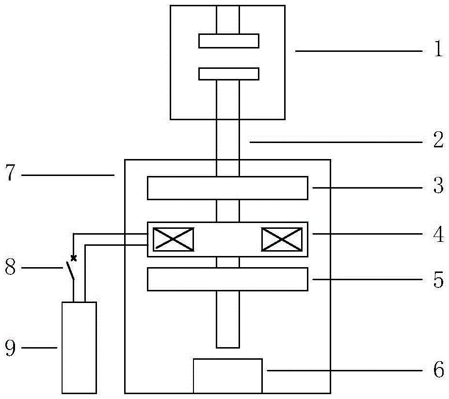
[0022] The present invention proposes a high-speed switch, such as figure 1 As shown, it consists of switch contact 1, connecting rod 2, repulsion operating mechanism, buffer 6, frame 7, closing and opening switch 8 and energy storage capacitor 9; the repulsion operating mechanism consists of opening repulsion plate 3, The repulsion coil 4 and the closing repulsion disc 5 are composed; the high-speed switch only needs one repulsion coil 4 to complete the closing and opening functions of the high-speed switch.

[0023] Wherein, the repulsion coil 4 is connected with the connecting rod 2, and the repulsion coil 4 will drive the connecting rod 2 to move together; the opening repulsion disk 3 and the closing repulsion disk 5 are respectively fixed on the frame 7. The repulsion coil 4 is placed b...


PUM


Abstract

The present invention relates to a high-speed switch. The switch comprises a switch contact, a connecting rod, a repulsion operating mechanism, a rack, a closing and breaking switch, and a power supply. The connecting rod is slidably connected to the rack, one end of the connecting rod is connected to a movable contact in the switch contact, and the other end of the connecting rod is arranged in a manner of running through the repulsion operating mechanism; the repulsion operating mechanism comprises a breaking repulsion disk, a repulsion coil and a closing repulsion disk which are sequentially arranged in parallel in the axial direction of the connecting rod; the breaking repulsion disk and the closing repulsion disk are separately fixed on the rack; the repulsion coil is fixed on the connecting rod; the power supply is connected with the repulsion coil through the closing and breaking switch to supply power; when the switch contact is at a breaking position, a gap between the repulsion coil and the closing repulsion disk is smaller than a gap between the repulsion coil and the breaking repulsion disk; and when the switch contact is at a closing position, the gap between the repulsion coil and the closing repulsion disk is greater than the gap between the repulsion coil and the breaking repulsion disk. By utilizing two principles that electromagnetic repulsion is sensitive to the sizes of the gaps between the repulsion coil and the repulsion disks, and the electromagnetic repulsion has short acting time, only one repulsion coil can complete closing and breaking.

Description

technical field [0001] The invention relates to the field of high-voltage switches, in particular to a high-speed switch. Background technique [0002] With the development of the power system, the power system has higher and higher requirements for power switches. The electromagnetic repulsion operating mechanism based on the principle of eddy current repulsion has become a research hotspot because of its outstanding advantages in rapidity and reliability. The repulsion operating mechanism has the advantages of simple structure, extremely fast action speed and high reliability, so it has been paid attention to and studied by scholars at home and abroad. [0003] The structure of the high-speed switch proposed in CN201310007542.7, CN200810056975.0, CN201010574242.3 and CN201310018005.2 can achieve the purpose of high-speed opening and closing. However, the structures involved in the above patents are two repulsive coils, and one repulsive disk is moved by force to complete...

Claims


Application Information

Patent Timeline
IPC IPC(8): H01H3/28H01H3/60
CPCH01H3/28H01H3/60
Inventor 赵羲英刘广义陈名
Owner CHINA XD ELECTRIC CO LTD
Why Eureka
Try Eureka