Composite magnetic pole type axial-flux permanent magnet synchronous motor

A technology of permanent magnet synchronous motor and axial flux, applied in synchronous machines, magnetic circuits characterized by magnetic materials, electrical components, etc., can solve problems such as motor performance degradation, irreversible demagnetization, harmonics, etc., and achieve improved reliability The effect of reducing the risk of demagnetization, reducing stator iron loss and torque fluctuation

Active Publication Date: 2016-03-23
HARBIN INST OF TECH
View PDF5 Cites 4 Cited by
  • Summary
  • Abstract
  • Description
  • Claims
  • Application Information

AI Technical Summary

Problems solved by technology

[0004] The purpose of the present invention is to solve the problems of harmonics and partial irreversible demagnetization in the air-gap magnetic field of rare earth permanent magnet synchronous motors driven by sine waves, especially under high temperature conditions, the irreversible demagnetization of permanent magnet materials will lead to the decline of motor performance , providing a combined pole type axial flux permanent magnet synchronous motor

Method used


Image

  • Composite magnetic pole type axial-flux permanent magnet synchronous motor
  • Composite magnetic pole type axial-flux permanent magnet synchronous motor
  • Composite magnetic pole type axial-flux permanent magnet synchronous motor

Examples


specific Embodiment approach 1

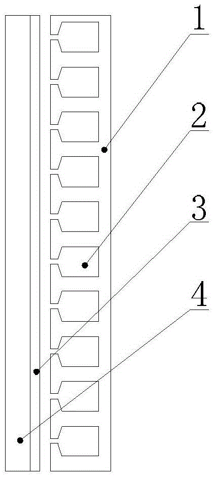
[0014] Specific implementation mode one: the following combination Figure 1 to Figure 5 Describe this embodiment. The combined magnetic pole type axial flux permanent magnet synchronous motor described in this embodiment includes a rotor and a stator, which are arranged in parallel and opposite each other. There is an axial air gap between the rotor and the stator. The stator includes a stator core 1 and a stator The winding 2, the stator core 1 is a disc-shaped structure, the stator winding 2 is arranged in the inner stator slot of the stator core 1; the rotor includes a plurality of rotor poles 3 and the rotor core 4, the rotor core 4 is a disc-shaped structure, and the rotor core 4 faces The surface of the stator is surface-mounted with a plurality of rotor poles 3 uniformly arranged along the circumferential direction;

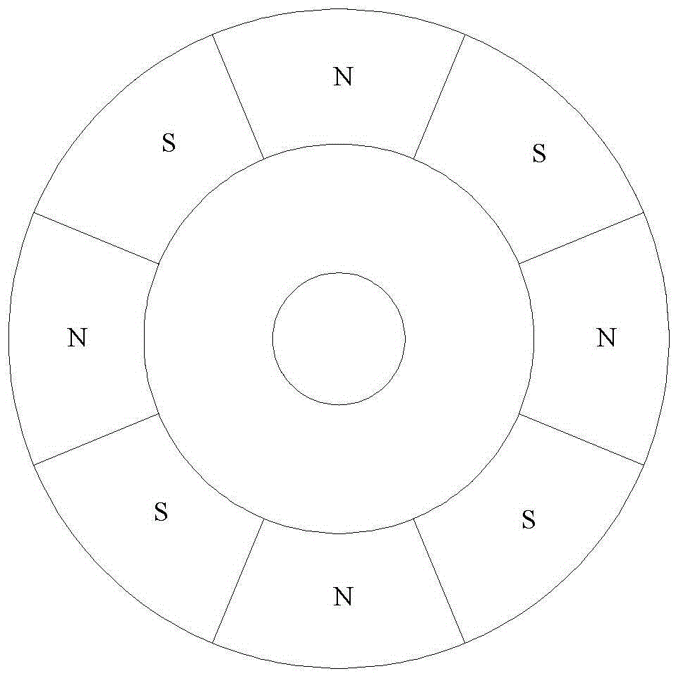
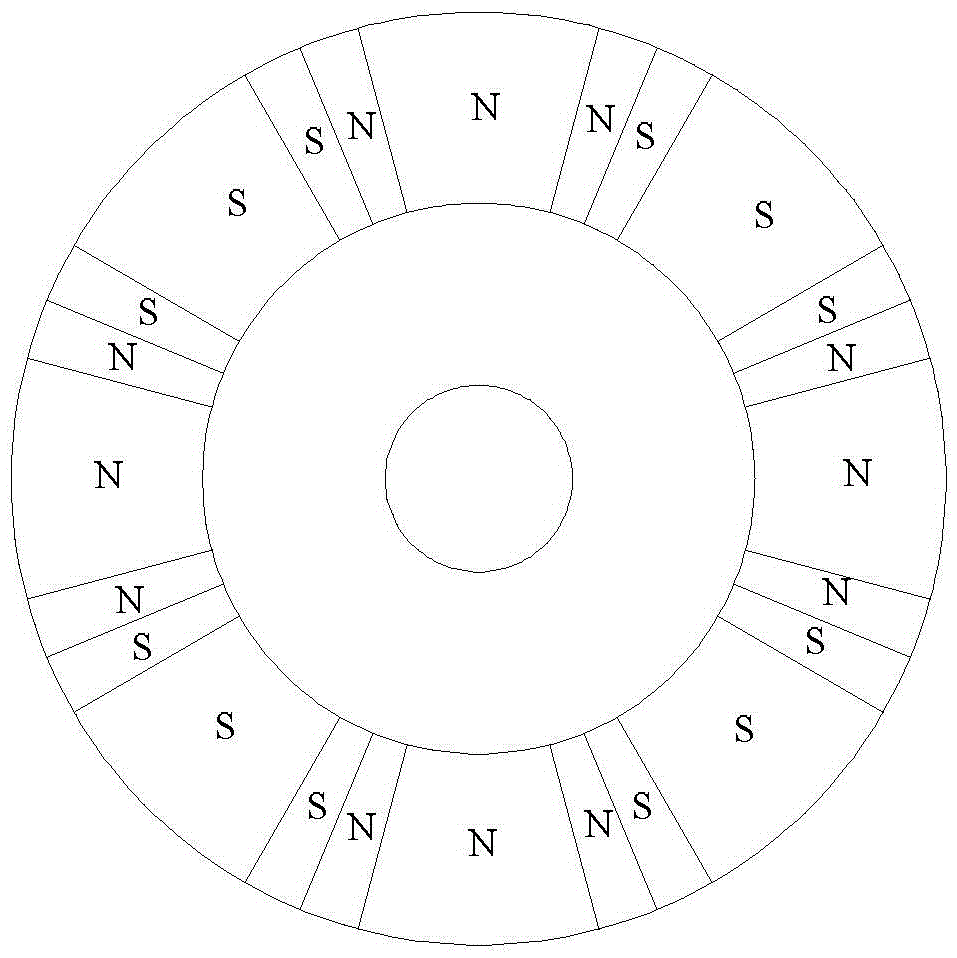
[0015] The rotor pole 3 has an arc-shaped structure, and the rotor pole 3 includes a rare earth permanent magnet pole 3-1 and two ferrite permanent magne...

specific Embodiment approach 2

[0019] Specific embodiment two: this embodiment further explains embodiment one, the arc angle of the rare earth permanent magnet pole 3-1 is a, the arc angle of the ferrite permanent magnet pole 3-2 is b / 2, and the two meet the following conditions :

[0020] a ( Br 2 ) 2 + b ( Br 1 ) 2 π - 2 π { 2 ...


PUM


Abstract

The invention discloses a composite magnetic pole type axial-flux permanent magnet synchronous motor, belongs to the field of permanent magnet motors, and aims at solving the problems that a harmonic wave exists in an air-gap magnetic field of a sine wave-driven rare-earth permanent magnet synchronous motor and local irreversible demagnetization easily occurs. The composite magnetic pole type axial-flux permanent magnet synchronous motor comprises a rotor and a stator, wherein the rotor and the stator are oppositely arranged in parallel; a plurality of rotor poles are evenly arranged on the surface, facing the stator, of a rotor core along the peripheral direction in a surface-mounted manner; the rotor poles are in an arc structure; each rotor pole comprises a rare-earth permanent magnet pole and two ferrite permanent magnet poles; one ferrite permanent magnet pole is arranged on each of the left end surface and the right end surface of each rare-earth permanent magnet pole; each rare-earth permanent magnet pole and each two ferrite permanent magnet poles form a continuous arc magnetic pole structure; and the magnetizing directions of the each rare-earth permanent magnet pole and each two ferrite permanent magnet poles all adopt axial magnetization and are the same. According to the permanent magnet synchronous motor with the structure, the harmonic content of the air-gap magnetic field is reduced; the motor efficiency is improved; meanwhile, the ferrite permanent magnet material is low in price; and the cost is reduced.

Description

technical field [0001] The invention relates to a combined magnetic pole type rotor structure, which belongs to the field of permanent magnet motors. Background technique [0002] With the increasingly serious problems of the environment and energy crisis, high-efficiency and energy-saving electrical equipment has become a development trend, which greatly promotes the development of high-power-density, high-efficiency rare earth permanent magnet synchronous motors. However, the price of rare earth permanent magnet materials has remained high, and rare earth permanent magnet motors are greatly affected by price fluctuations of rare earth permanent magnet materials, so the cost of rare earth permanent magnet motors is also affected. The development space of magnetic synchronous motor. Moreover, rare earth materials are non-renewable resources, and excessive use of rare earth materials in motor systems will also cause damage to the environment. Therefore, under the premise of...

Claims


Application Information

Patent Timeline
Patent Type & Authority Applications(China)
IPC IPC(8): H02K21/00H02K1/02
CPCH02K1/02H02K21/00
Inventor 佟诚德程路明宋志翌王明峤田孟娇
Owner HARBIN INST OF TECH
Why Eureka
Try Eureka