Hybrid excitation double-stator switched reluctance motor

A technology of switched reluctance motor and mixed excitation, which is applied in synchronous machines, electrical components, electromechanical devices, etc., to achieve the effects of reducing core loss, increasing power density, and reducing the risk of demagnetization

Active Publication Date: 2020-12-15
JIANGSU UNIV
View PDF15 Cites 2 Cited by
  • Summary
  • Abstract
  • Description
  • Claims
  • Application Information

AI Technical Summary

Problems solved by technology

[0003] The purpose of the present invention is to solve the problems existing in the existing hybrid excitation switched reluctance motor, and to propose a method that can increase the power of the motor without reducing the space of the stator winding, without the risk of demagnetization of the permanent magnet, and without increasing the eddy current loss. Mixed excitation double stator switched reluctance motor with density and torque

Method used


Image

  • Hybrid excitation double-stator switched reluctance motor
  • Hybrid excitation double-stator switched reluctance motor
  • Hybrid excitation double-stator switched reluctance motor

Examples


Embodiment Construction

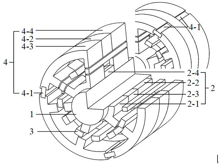
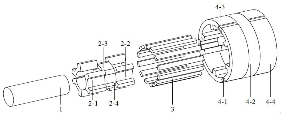
[0021] see figure 1 and figure 2 , a hybrid excitation dual-stator switched reluctance motor proposed by the present invention includes a fixed shaft 1 , a hybrid inner stator 2 , a rotor 3 , a hybrid outer stator 4 , an inner winding 5 and an outer winding 6 . In the middle is the fixed shaft 1, the hybrid inner stator 2, the rotor 3 and the hybrid outer stator 4 are coaxially nested in sequence from the inside to the outside along the radial direction, the hybrid inner stator 2 is fixedly sleeved outside the fixed shaft 1, and the hybrid inner stator 2 and the rotor 3 A radial air gap is left between them, and a radial air gap is left between the rotor 3 and the mixing outer stator 4.

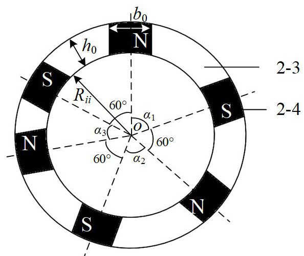
[0022] The hybrid inner stator 2 is composed of a left inner stator 2-1, a right inner stator 2-2, a magnetic isolation block 2-3 and an axially magnetized inner stator permanent magnet 2-4. recombine image 3 As shown, the magnetic isolation blocks 2-3 and the inner stator permanent magn...


PUM


Abstract

The present invention discloses a hybrid excitation double-stator switched reluctance motor. Six magnetism isolating blocks and six inner stator permanent magnets are embedded in a staggered mode in the circumferential direction to form a cylinder, and the left inner stator and the right inner stator which are the same in structure are arranged on the two axial end sides of the magnetism isolatingblocks and the two axial end sides of the inner stator permanent magnets respectively and are symmetrical in the axial direction. The left side inner stator and the right side inner stator are each composed of three inner stator blocks which are the same in structure and are unevenly arranged in the circumferential direction, and the left side outer stator and the right side outer stator which are the same in structure are arranged on the axial end side of the middle outer stator respectively, are symmetrical in the axial direction and are each composed of three outer stator blocks arranged in the circumferential direction. Side teeth are arranged at the end of each outer stator block in the circumferential direction, an outer stator permanent magnet is fixedly embedded between every twoadjacent side teeth, each outer stator permanent magnet is magnetized in the tangential direction of the circumference, an inner winding is wound on each inner stator salient pole tooth, and an outerwinding is wound on each outer stator salient pole tooth. Under the condition that the same exciting current flow in, the output torque is increased, and the motor power density is improved.

Description

technical field [0001] The invention belongs to the technical field of motor structure, in particular to a double-stator switched reluctance motor. Background technique [0002] Due to its simple and solid structure, low manufacturing cost, high reliability, and high efficiency, switched reluctance motors occupy a certain market share in the fields of servo, electric vehicle drive, and general industry. The traditional switched reluctance motor has the problem of low current power density because it has no permanent magnet and only relies on electric excitation. In response to this problem, a hybrid excitation switched reluctance motor has been proposed, such as the motor proposed in the Chinese Patent Publication No. CN104935095A, named "A U-shaped Stator Hybrid Excitation Switched Reluctance Motor", which adopts a modular U-shaped stator. The inner side of the U-shaped stator is provided with tangentially magnetized permanent magnets, and the two stator teeth of the stato...

Claims


Application Information

Patent Timeline
Patent Type & Authority Applications(China)
IPC IPC(8): H02K16/04H02K21/38H02K21/04H02K1/17H02K1/14
CPCH02K16/04
Inventor 孙晓东凤丽云陈龙周卫琪田翔
Owner JIANGSU UNIV
Why Eureka
Try Eureka