Rotor punching sheet, rotor and motor using rotor punching sheet and rotor

A technology of rotor punching and magnetic steel grooves, applied in electrical components, electromechanical devices, magnetic circuit rotating parts, etc., can solve the problems of increasing reluctance torque, increasing the proportion of quadrature inductance, etc. Demagnetization, increase reluctance torque component, good stability

Pending Publication Date: 2022-01-18
ZHEJIANG ZHONGCHE SHANGCHI ELECTRIC CO LTD
View PDF0 Cites 2 Cited by
  • Summary
  • Abstract
  • Description
  • Claims
  • Application Information

AI Technical Summary

Problems solved by technology

[0003] Aiming at the deficiencies of the prior art, the present invention provides a U+1 topology rotor punching structure, through the optimization of the auxiliary slot and the magnetic isolation bridge, the proportion of the quadrature axis inductance can be increased, and the reluctance torque can be increased, ensuring On the basis of the output torque of the motor, it can reduce the production cost of the motor, effectively improve the sine degree of the air gap magnetic field, reduce harmonics, and improve the problem of vibration and noise, so as to achieve high performance and low cost motor design

Method used


Image

  • Rotor punching sheet, rotor and motor using rotor punching sheet and rotor
  • Rotor punching sheet, rotor and motor using rotor punching sheet and rotor
  • Rotor punching sheet, rotor and motor using rotor punching sheet and rotor

Examples


Embodiment Construction

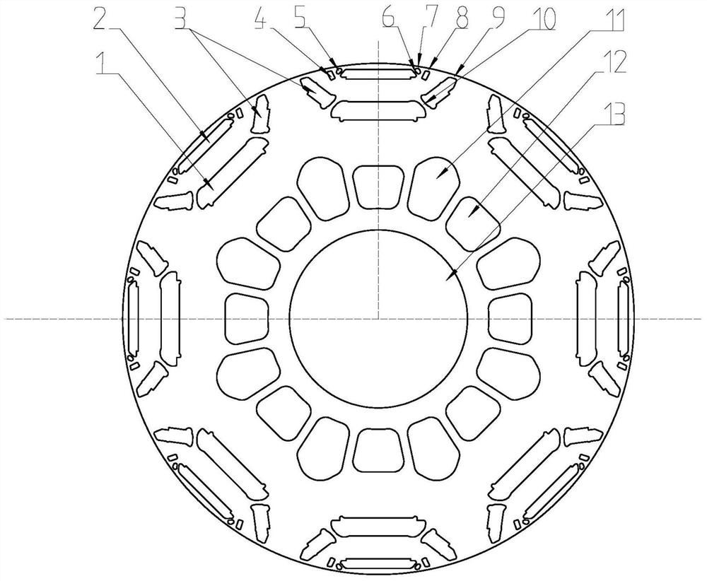
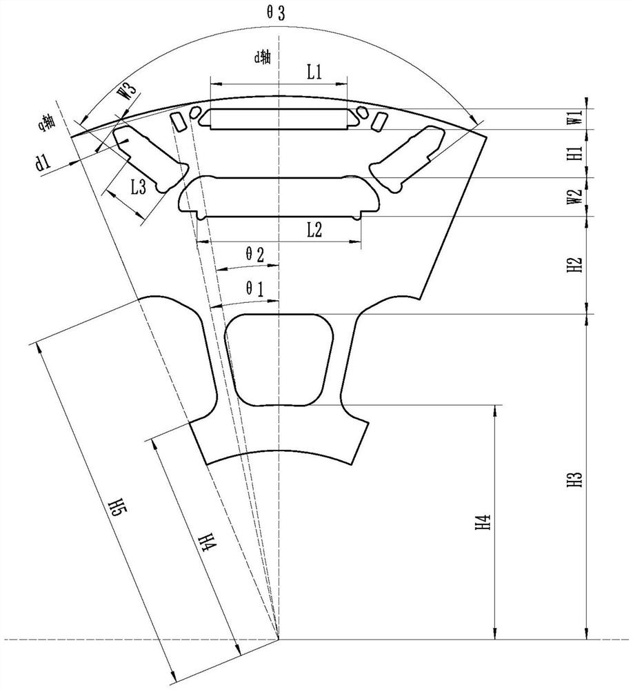
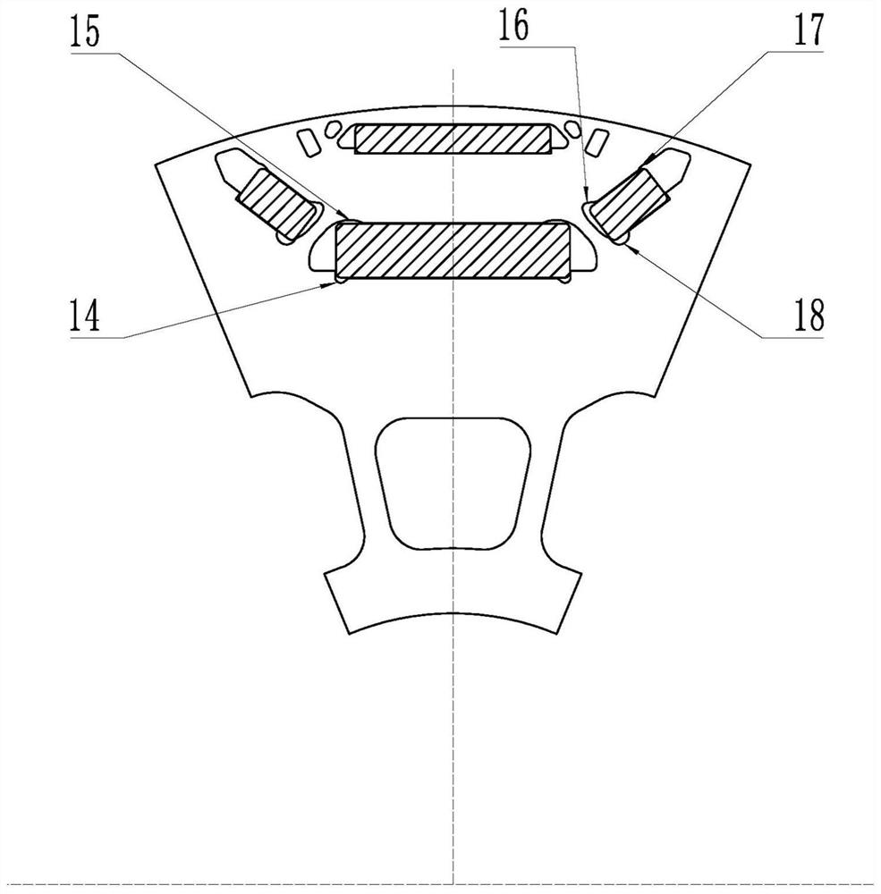
[0042] refer to Figure 1 to Figure 6 The embodiment of the rotor sheet, the rotor and the motor to which they are applied will be further described.

[0043] In the description of the present invention, it should be noted that for orientation words, such as the term "center", "horizontal (X)", "longitudinal (Y)", "vertical (Z)", "length", " Width", "Thickness", "Top", "Bottom", "Front", "Back", "Left", "Right", "Vertical", "Horizontal", "Top", "Bottom", "Inner ", "outside", "clockwise", "counterclockwise" and other indication orientations and positional relationships are based on the orientation or positional relationship shown in the drawings, and are only for the convenience of describing the present invention and simplifying the description, rather than indicating or implying the Means that a device or element must have a specific orientation, be constructed and operated in a specific orientation should not be construed as limiting the specific protection scope of the pre...


PUM


Abstract

The invention discloses a rotor punching sheet, which comprises a plurality of magnetic pole areas distributed along the circumference, first magnetic steel grooves and second magnetic steel grooves are arranged in the magnetic pole areas, the first magnetic steel grooves are located at the outer sides of the second magnetic steel grooves, and the midperpendicular of the first magnetic steel grooves and the midperpendicular of the second magnetic steel grooves coincide, and the rotor punching sheet also comprises two third magnetic steel grooves, the two third magnetic steel grooves are distributed at the two ends of the second magnetic steel groove and are symmetrically arranged in a V shape, values of the width L1 of the first magnetic steel groove, the width L2 of the second magnetic steel groove and the width L3 of the third magnetic steel grooves meet the following relation, r1 is the radius of the outermost circle of the rotor punching sheet, and p is the number of pole pairs of the motor; the value of the thickness W1 of the first magnetic steel groove, the value of the thickness W2 of the second magnetic steel groove and the value of the thickness W3 of the third magnetic steel groove meet the following relation: 0.16 * L1 < = W1 < = 0.2 * L1 < = W2 < = 2 * W1 < = W3 < = W2; and on the basis of ensuring the output torque of the motor, the production cost of the motor can be reduced, the sine degree of an air-gap magnetic field is effectively improved, harmonic waves are reduced, and the vibration noise problem is improved, so that the high-performance and low-cost motor design is realized.

Description

technical field [0001] The invention belongs to the technical field of electric motors, and more specifically relates to a rotor stamping sheet, a rotor and an applied electric motor. Background technique [0002] Permanent magnet synchronous motors have been widely used in the field of new energy vehicles due to their high power density, high efficiency, and wide field-weakening speed regulation capability, and they have become dominant at present. With the popularization and application of new energy vehicles, the competition in performance and cost is increasing. There are a variety of topological structures of rotor punching in the market. The flat-shaped magnet is suitable for motors with relatively small circles. When the circle is large, The straight shape is not suitable, the stress distribution will increase, and the magnetic concentration effect will decrease. The U+1 rotor topology adds V-shaped magnetic steel on both sides of the double one, which can produce a ...

Claims


Application Information

Patent Timeline
Patent Type & Authority Applications(China)
IPC IPC(8): H02K1/22H02K1/27H02K29/03
CPCH02K1/22H02K1/27H02K2213/03H02K29/03
Inventor 唐小春于冰贾梦凡
Owner ZHEJIANG ZHONGCHE SHANGCHI ELECTRIC CO LTD
Why Eureka
Try Eureka