
A Method of Improving the Dynamic Range of Data Acquisition System

A data acquisition system and dynamic range technology, applied in the direction of analog-to-digital converter, analog-to-digital conversion, electrical components, etc., can solve the problems of limited improvement of dynamic range, unfavorable engineering implementation, and surge in cost, so as to improve the dynamic range. , to ensure the quantization accuracy, the effect of increasing the amplitude range

Active Publication Date: 2018-09-04
陕西海泰电子有限责任公司
View PDF4 Cites 0 Cited by
  • Summary
  • Abstract
  • Description
  • Claims
  • Application Information

AI Technical Summary

Problems solved by technology

This method of simply increasing the number of ADCs has a limited improvement in the dynamic range of the system. When the number of ADCs is doubled, the dynamic range can only be increased by 6dB. If there are many ADCs that are sampled in parallel, it will bring difficulties in wiring synchronization. And the surge in cost is not conducive to the actual engineering realization

Method used


Image

  • A Method of Improving the Dynamic Range of Data Acquisition System
  • A Method of Improving the Dynamic Range of Data Acquisition System

Examples


Embodiment 1

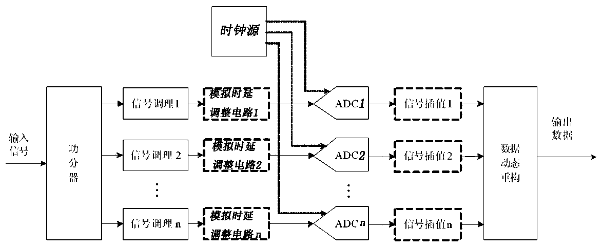
[0027] Take n=2 two-channel parallel sampling system as an example:

[0028] The received analog signal is sent to the power divider, divided into two parallel signals, and the amplitude of the two signals is respectively scaled. That is, channel 1 is connected to ADC1 after passing through signal conditioning circuit 1 and analog delay adjustment circuit 1 in sequence; channel 2 is connected to ADC2 after passing through signal conditioning circuit 2 and analog delay adjustment circuit 2 in sequence; among them, signal conditioning circuit 1 is an attenuation circuit connected in sequence A device and a limiter 1, a signal conditioning circuit 2 are a programmable gain amplifier and a limiter 2 connected in sequence. Among them, the size of limiter 1 and limiter 2 is set to the full-scale value of ADC. That is, channel 1 compresses the amplitude of the signal through the attenuator 1, and channel 2 amplifies the amplitude of the signal through the programmable gain amplifier...

Embodiment 2

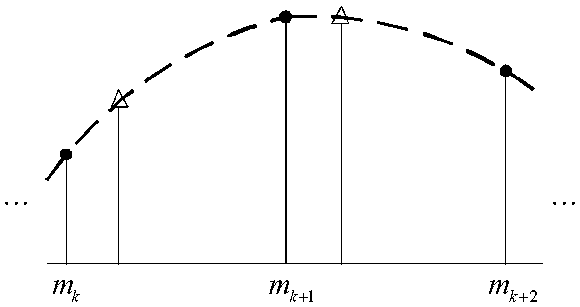
[0033] The difference from Embodiment 1 is that under the high-speed data acquisition system, the synchronization accuracy is required to be improved, and after the adjustment of the analog delay adjustment circuit, a certain delay or phase error may still remain. In this case, adjustments can be made in the digital domain by means of digital signal processing. The delay of integral multiple sampling intervals can be corrected by data cache alignment; for fractional delays less than 1 sampling interval, it needs to be adjusted by data interpolation, such as figure 2 As shown, that is, the sampling point at the correct position generated by the raw sampling data of the data acquisition system. Other steps are identical with embodiment 1.


PUM


Abstract

The invention belongs to the technical field of data acquisition, and more particularly relates to a method for extending a dynamic range of an analog-digital converter (ADC) in a data acquisition system. The method for extending the dynamic range of the data acquisition system comprises following steps of equally dividing an analog signal received by the data acquisition system into n paths of parallel signals, wherein n is greater than or equal to 2; performing unequal amplitude scaling on each path of parallel signal, and then connecting each path of parallel signal with an ADC; and recovering data parallelly sampled and quantified by a plurality of paths of ADCs into single path of sampling signal through corresponding amplitude recovery and data dynamic reconstruction algorithm in a digital domain. According to the method, fewer ADCs are adopted, and the amplitude range of the quantifiable signal is extended; in addition, quantification accuracy of small signals is guaranteed, both high sampling rate and high resolution of a single ADC are guaranteed, and the dynamic range of the data acquisition system is extended.

Description

technical field [0001] The invention belongs to the technical field of data acquisition, and in particular relates to a method for improving the dynamic range of an analog-to-digital converter (ADC) in a data acquisition system. Background technique [0002] The dynamic range of a data acquisition system is the ratio of the largest signal to the smallest signal that the ADC can quantify. ADC is the core unit in the data acquisition system, its highest sampling rate directly affects the bandwidth of the acquisition system, and the resolution plays a decisive role in the dynamic range of the acquisition system. In reality, due to the limitation of the realization principle and manufacturing process of the ADC device, its sampling rate and resolution are always a pair of contradictory indicators. In order to overcome the contradictory and restrictive relationship between sampling rate and resolution, ADC parallel sampling technology based on multi-channel has been applied to a...

Claims


Application Information

Patent Timeline
Patent Type & Authority Patents(China)
IPC IPC(8): H03M1/18
CPCH03M1/188
Inventor 郭恩全李春滨苗胜刘雪芬
Owner 陕西海泰电子有限责任公司
Learn More