Graduation brightness adjusting system

A brightness adjustment and rectifying resistor technology, which is applied in the field of reticle brightness adjustment system, can solve problems such as visual fatigue of users, uneven brightness, narrow brightness adjustment range, etc., achieve high adjustment accuracy, avoid light and dark fluctuations, and shorten aiming time Effect

Inactive Publication Date: 2016-03-23
河南平原光电有限公司
View PDF5 Cites 0 Cited by
  • Summary
  • Abstract
  • Description
  • Claims
  • Application Information

AI Technical Summary

Problems solved by technology

[0002] In the dark background with insufficient light such as at night, when using optical equipment for measurement or aiming, it is required that the measuring tool itself must have the necessary lighting function to ensure that the operator can clearly and accurately identify the corresponding position of the target object on the measuring tool. Various types of scale data are read, but due to the great variability in light distribution and target reflective performance, it is necessary to have the ability to flexibly adjust the brightness of the optical pointing and measuring equipment used to adjust the brightness of the target. , in order to solve this problem, the brightness adjustment function of the reticle lighting of the traditional optical aiming and measuring equipment mainly realizes the purpose of controlling the brightness of the reticle lighting by adjusting the resistance value of the current-limiting potentiometer. Although the traditional adjustment method can be used to a certain extent However, it also has a relatively narrow brightness adjustment range, and at the same time, it is difficult to grasp the best brightness potentiometer resistance range, and the control accuracy is poor, so it is extremely difficult to adjust the potentiometer resistance to the best value at one time. The brightness resistance range requires repeated adjustment and verification many times, resulting in uneven brightness during the adjustment process, and obvious flickering or flickering fluctuations are easy to appear. On the one hand, the efficiency of the measurement work is greatly reduced, and on the other hand On the other hand, it is easy to cause visual fatigue of users, and long-term use is easy to cause serious damage to the eyesight of users. Therefore, it is urgent to develop a new reticle brightness adjustment system to overcome many shortcomings of traditional equipment.

Method used


Image

  • Graduation brightness adjusting system

Examples


Embodiment Construction

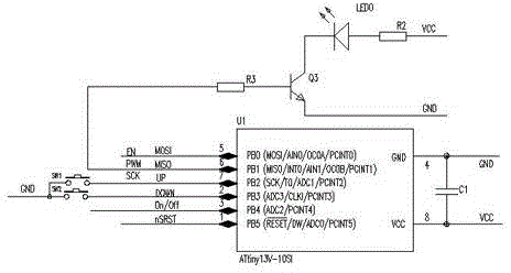
[0011] like figure 1 As shown, a reticle brightness adjustment system is composed of a control circuit, a filter circuit and a lighting circuit, wherein the control circuit is composed of a control chip and an input circuit, and the control chip ATINY13V-10SI is provided with PB0, PB1, PB2, PB3, PB4 and PB5 has a total of six signal processing ports, one ground port GND and one power port VCC. The input circuit has two adjustment keys SW1 and SW2, and the two adjustment keys SW1 and SW2 in the input circuit are respectively connected to the control chip ATINY13V—10SI Connect to PB2 and PB3 ports on the top, connect to PB1 port on the lighting circuit control chip ATINY13V-10SI, and connect the control chip ATINY13V-10SI to the filter circuit through the ground port GND and the power port VCC. The filter circuit is composed of at least one capacitor C1, and is connected to The power supply VCC and the circuit ground node GND are connected. The lighting circuit is composed of a ...


PUM


Abstract

The invention discloses a graduation brightness adjusting system, which includes a control circuit, a filter circuit and an illumination circuit. The control circuit includes a control chip and an input circuit. The control chip is at least provided with six signal processing ports, a grounding port and a power supply port. The input circuit is provided with at least two adjusting keys. The filter circuit is formed by at least one capacitor. The illumination circuit is formed by an illuminating lamp unit, a rectification resistor and a triode. The graduation brightness adjusting system has the characteristics of wide adjusting intervals and high adjusting precision. The success rate enabling proper brightness to be adjusted well once is greatly increased, so the observation efficiency is improved, and the aiming time is shortened. Moreover, a drawback of obvious brightness fluctuation is overcome, visual fatigue of an operator is effectively alleviated and the eyesight of the operator is protected.

Description

technical field [0001] The invention relates to a division brightness adjustment system, which belongs to the technical field of observation photoelectric application. Background technique [0002] In the dark background with insufficient light such as at night, when using optical equipment for measurement or aiming, the measuring tool itself must have the necessary lighting function to ensure that the operator can clearly and accurately identify the corresponding position of the target object on the measuring tool. Various types of scale data are read, but due to the great variability in light distribution and target reflective performance, it is necessary to have the ability to flexibly adjust the brightness of the optical pointing and measuring equipment used to adjust the brightness of the target. , in order to solve this problem, the brightness adjustment function of the reticle lighting of the traditional optical aiming and measuring equipment mainly realizes the purpo...

Claims


Application Information

Patent Timeline
Patent Type & Authority Applications(China)
IPC IPC(8): H05B37/02
CPCY02B20/40
Inventor 张龙曲雅臣朱怀兵李帅张金涛夏树策马英连海根李俭韩家营
Owner 河南平原光电有限公司
Why Eureka
Try Eureka