Needle glue removing mechanism and dispenser

A technology of clearing glue and needles, which is applied in the field of glue dispensing machines, can solve the problems of affecting the precision of dispensing glue, slow cleaning speed, and affecting product quality, etc., and achieve the effect of improving operation quality, improving cleanliness, and shortening operation time

Active Publication Date: 2016-03-30
SUZHOU SECOTE PRECISION ELECTRONICS CO LTD
View PDF6 Cites 19 Cited by
  • Summary
  • Abstract
  • Description
  • Claims
  • Application Information

AI Technical Summary

Problems solved by technology

The volume of modern electronic products is getting smaller and smaller. When fixing its components, relying solely on the form of fastener connection can no longer meet the demand. Therefore, it is now common to use glue dispensers to glue and fix electronic products.
[0003] However, after the dispensing machine has been used for a period of time, there will be residual glue on the dispensing needle, and when there is a lot of residual glue, it will affect the dispensing accuracy, thereby affecting product quality; in addition, the residual glue will solidify when it contacts with air for a long time, resulting The needle nozzle is blocked, which is not conducive to the follow-up operation, so the needle residue glue must be cleaned in time when dispensing glue
The existing cleaning methods are generally cleaned by manual wiping, which not only needs to stop the machine and disassemble the needle, but also has a slow cleaning speed and is not clean, which greatly affects the production efficiency
Of course, there are also some automatic glue cleaning devices in the prior art, such as a mechanism that uses glue blowing to clean up. This kind of mechanism is difficult to ensure the quality of work, and it will also cause pollution to the working environment.

Method used


Image

  • Needle glue removing mechanism and dispenser
  • Needle glue removing mechanism and dispenser
  • Needle glue removing mechanism and dispenser

Examples


Embodiment Construction

[0027] The present invention will be further described in detail below in conjunction with the accompanying drawings and embodiments. It should be understood that the specific embodiments described here are only used to explain the present invention, but not to limit the present invention. In addition, it should be noted that, for the convenience of description, the drawings only show some but not all structures related to the present invention, and the drawings are only for the purpose of illustration, and are not drawn according to the original scale.

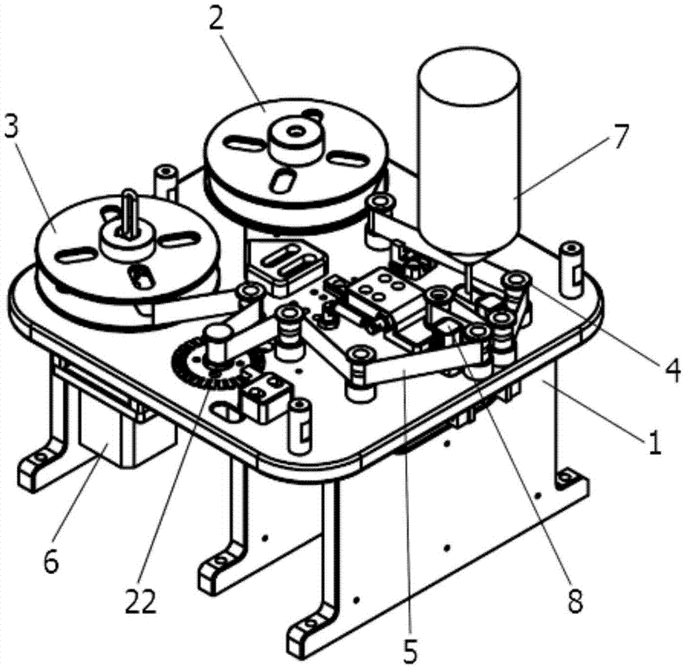
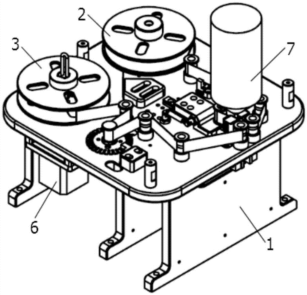
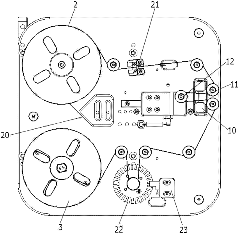
[0028] like Figure 1-Figure 3 As shown, the present embodiment provides a needle glue clearing mechanism, including a machine platform 1, and a raw material tray 2 fixed on the machine platform 1, a receiving tray 3 and a pulley block 4, wherein the shaft of the raw material tray 2 is equipped with a roll The material belt 5, one end of the material belt 5 is drawn from the raw material tray 2 and then bypasses each pulley ...


PUM


Abstract

The invention discloses a needle glue removing mechanism which comprises a cabinet, wherein a material tray, a material receiving tray and a pulley block are fixed on the cabinet; a material band is rolled in the material tray, and one end of the material band is led out from the material tray and then sequentially passes each pulley of the pulley block to be connected with the material receiving tray; the bottom of the material receiving tray is connected with a stepping motor, and the stepping motor drives the material receiving tray to rotate, so that the material band is rolled into the material receiving tray; and at least three pulleys in the pulley block fold the material band into U shape, the middle of the U-shaped material band is used for insertion of a to-be-cleaned dispenser needle, and two sides of the U-shaped material band are respectively provided with a chuck which is used for clamping the material band and the needle. According to the invention, the stepping motor is used for driving the material receiving tray and the material band to move, and due to clamping friction of the material band and the needle, residual glue on the needle can be cleaned up, thus overcoming inconvenience of manual operation, realizing automatic cleaning of the needle, and greatly improving the working quality; and since a material rolling form is adopted, used material band can be recycled in rolls, pollution of the field due to production of rubbish can be avoided, and the cleanness of the working environment can be improved.

Description

technical field [0001] The invention relates to the technical field of glue dispensing machines, in particular to a needle glue clearing mechanism and a glue dispenser with the needle glue clearing mechanism. Background technique [0002] With the development of society, rising labor costs and the rise of the automation industry, the widespread use of automation equipment has become an irreplaceable trend. The vigorous promotion of automation equipment, an important tool, can not only save a lot of manpower and material resources for various industries, but also greatly improve product quality and increase output value benefits. The size of modern electronic products is getting smaller and smaller. When fixing its parts, relying solely on the form of fastener connection can no longer meet the demand. Therefore, glue dispensers are now commonly used to glue and fix electronic products. [0003] However, after the dispensing machine has been used for a period of time, there w...

Claims


Application Information

Patent Timeline
Patent Type & Authority Applications(China)
IPC IPC(8): B05C5/02B05B15/02
CPCB05B15/52B05C5/02
Inventor 孙丰
Owner SUZHOU SECOTE PRECISION ELECTRONICS CO LTD
Why Eureka
Try Eureka