
Lifting-free electric tool rest

A tool holder, electric technology, applied in metal processing equipment and other directions, can solve the problems of poor sealing of the tool holder, parts that do not meet the requirements of use, poor impact resistance, etc., and achieve the effect of solving sealing problems, reasonable design, and eliminating interference.

Inactive Publication Date: 2016-03-30
陆如东
View PDF6 Cites 2 Cited by
  • Summary
  • Abstract
  • Description
  • Claims
  • Application Information

AI Technical Summary

Problems solved by technology

The current domestic vertical electric CNC tool post has the following disadvantages: 1. Poor impact resistance and poor rigidity during the cutting process, and parts with high machining accuracy cannot meet the requirements for use; 2. When the upper knife needs to be lifted, the tool post Poor sealing

Method used


Image

  • Lifting-free electric tool rest

Examples


Embodiment Construction

[0014] The present invention will now be further described in conjunction with the accompanying drawings and preferred embodiments. These drawings are all simplified schematic diagrams, which only illustrate the basic structure of the present invention in a schematic manner, so they only show the configurations related to the present invention.

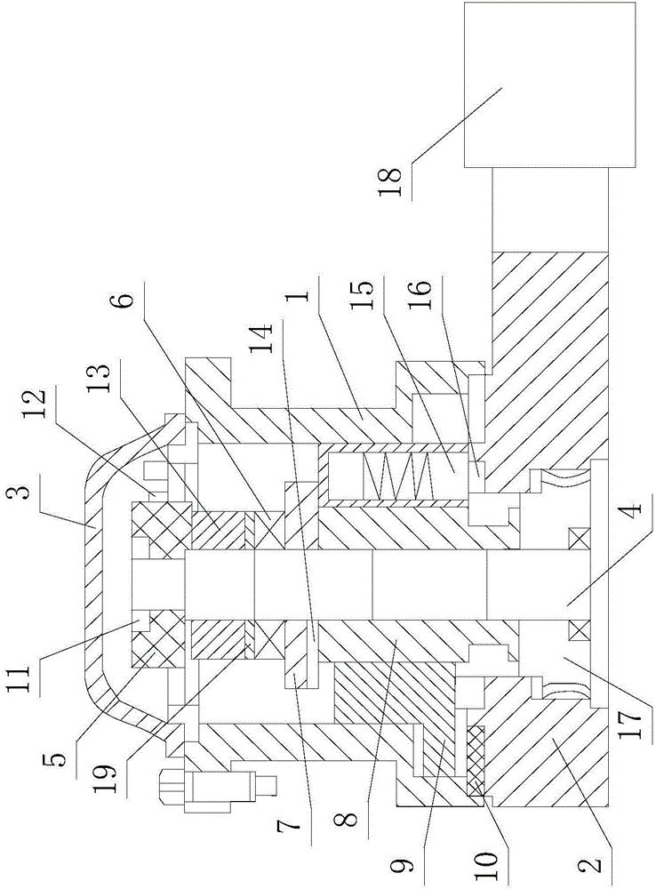
[0015] like figure 1 The lift-free electric knife holder shown includes an upper knife body 1 and a lower knife body 2 arranged up and down, and an upper cover 3 is arranged above the upper knife body 1, and the upper knife body 1 and the lower knife body 2 are in contact with each other. The outer end teeth 10 are arranged on the part, and the central axis 4 is vertically arranged in the center of the cavity formed by the upper cover 3, the upper cutter body 1 and the lower cutter body 2; , large nut 13, stop ring 6, clutch disc 7, screw rod 8 and worm wheel 17, clutch pin 14 is installed at the bottom of clutch disc 7; one side of ...


PUM


Abstract

The invention relates to the technical field of machine tool accessories, in particular to a lifting-free electric tool rest which is installed on a machine tool or a tool sharpener. The lifting-free electric tool rest comprises an upper tool body and a lower tool body, wherein the upper tool body is arranged above the lower tool body. An upper cover is arranged on the upper tool body. A center shaft is perpendicularly arranged in the center of a cavity formed by the upper cover, the upper tool body and the lower tool body. The center shaft is sequentially sleeved with a transmitting disc, a big nut, a retaining ring, a clutch disc, a screw and a worm gear from top to bottom. A clutch pin is installed at the bottom of the clutch disc. A clutch disc groove is formed in one side of the screw. A counter pin is arranged on the other side of the screw. A counter disc groove is fixed to the bottom end of the counter pin. A Hall element is installed on one side of the transmitting disc. The lifting-free electric tool rest is reasonable in design; the upper tool body does not need to be lifted during transposition of the upper tool body, so that intrusion caused by cooling and cuttings during transposition of the tool rest is eliminated, and sealing of the tool rest is achieved thoroughly and reliably.

Description

technical field [0001] The invention relates to the technical field of machine tool accessories, in particular to a lift-free electric tool holder installed on a machine tool or a knife grinder. Background technique [0002] At present, the tool holders equipped with economical CNC horizontal lathes are mainly vertical electric CNC tool holders. The CNC tool post works in the harshest environment of the CNC lathe. The vibration of cutting, the strong impact of chip breaking cutting, the frequent indexing of the tool post, the heat conduction of the cutting process, etc. require the CNC tool post to have high comprehensive mechanical properties. The current domestic vertical electric CNC tool post has the following disadvantages: 1. Poor impact resistance and poor rigidity during the cutting process, and parts with high machining accuracy cannot meet the requirements for use; 2. When the upper tool needs to be lifted, the tool post Poor sealing. Contents of the invention ...

Claims


Application Information

Patent Timeline
Patent Type & Authority Applications(China)
IPC IPC(8): B23B21/00
Inventor 陆如东
Owner 陆如东
Learn More