Augmented reality display system

A display system and augmented reality technology, applied in the field of optics, can solve problems such as poor viewing experience, affecting imaging quality, uneven light matching, etc., to achieve the effect of avoiding light crosstalk, excellent filter characteristics, and improving experience comfort

Pending Publication Date: 2021-02-26
SVG TECH GRP CO LTD +1
View PDF0 Cites 2 Cited by
  • Summary
  • Abstract
  • Description
  • Claims
  • Application Information

AI Technical Summary

Problems solved by technology

However, the above situation is an ideal situation. In the process inspection process, the light matched with the first diffractive waveguide lens 1-1 cannot be completely diffracted and transmitted by the lens, and part of the light will continue to pass through the second diffractive waveguide lens 1-2 and the third diffractive waveguide lens 1-2. Diffractive waveguide lenses 1-3 conduct with weak efficiency inside and reflect between two diffractive waveguide lenses, which will form interference light, cause uneven matching of light, and ultimately affect image quality, resulting in poor viewing experience

Method used


Image

  • Augmented reality display system
  • Augmented reality display system
  • Augmented reality display system

Examples


Embodiment 1

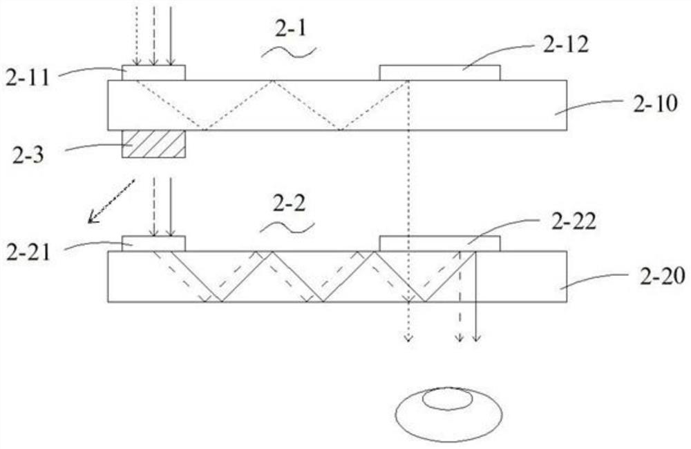
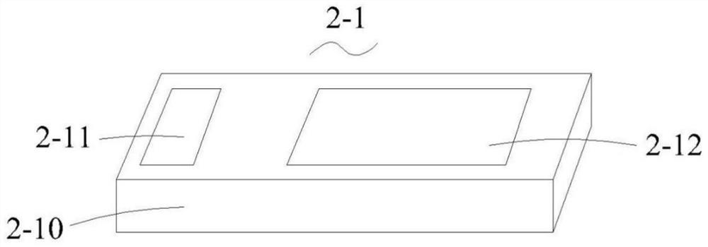
[0034] See figure 2 , image 3 with Figure 5 , the augmented reality display system shown in an embodiment of the present invention includes:

[0035] A laser light source (not shown) is used to provide incident image light. Of course, in other embodiments, it can also be other light sources such as LED, LCD or OLED. A first diffractive waveguide lens 2-1 and a second diffractive waveguide lens 2-2 are arranged at the irradiation place of the laser light source, and each diffractive waveguide lens includes a lens body and a functional area arranged on the lens body, specifically: the first The diffractive waveguide lens 2-1 includes a first lens body 2-10, a first coupling region 2-11 disposed on the first lens body 2-10, and a first coupling region 2-10 disposed on the first lens body 2-10. out of the region 2-12; the second diffractive waveguide lens 2-2 includes a second lens body 2-20, a second coupling region 2-21 disposed on the second lens body 2-20, and a second l...

Embodiment 2

[0040] See Image 6 , in this embodiment, other structures of the augmented reality display system of the present invention are the same as those in Embodiment 1, except that the diffractive optical structure set on the filter layer in this embodiment is a blazed grating, specifically, the incident When light is incident on a blazed grating at an angle α, the diffracted light exits at an angle β. By designing the groove spacing and blaze angle of the blazed grating, the blazed grating can achieve the maximum diffraction efficiency at a specific diffraction order for a specific wavelength, while achieving the lowest diffraction efficiency at other orders, especially the zero order. The optical filter layer of the present invention adopts the blazed grating design, which can achieve the maximum diffraction efficiency diffraction for light of a specific wavelength, while the rest of the wavelength bands are not affected and do not participate in the diffraction, and continue to b...

Embodiment 3

[0042] See Figure 7 with Figure 8 , in this embodiment, other structures of the augmented reality display system of the present invention are the same as those in Embodiment 1, except that the diffractive optical structure provided on the filter layer in this embodiment is a diffractive optical element. Specifically, Diffractive optical elements are also called binary optical elements, according to the general calculation formula of the diffraction efficiency of binary optical elements:

[0043]

[0044] Among them, N is the step number of the binary optical element, and m is the diffraction order. In ordinary diffraction gratings, the zero-order diffraction efficiency occupies a large energy ratio. By controlling the depth and size of the structure, the binary optical element can make the diffraction efficiency of the diffracted light under the incident condition of a specific wavelength be 0 when m=0, that is, the diffraction order is zero, that is to say, the zero-or...


PUM


Abstract

The invention relates to an augmented reality display system, which comprises a light source, at least two diffractive waveguide lenses and a light filtering layer, wherein the light source is used for providing image light; each of the at least two diffractive waveguide lenses comprises a lens body and a functional area arranged on the lens body; and the at least one light filtering layer used for enabling unnecessary light to generate light deflection is arranged between the two diffractive waveguide lenses, and a diffractive optical structure is arranged on the light filtering layer. According to the augmented reality display system, the light filtering layer is arranged between every two diffractive waveguide lenses, so that independent control of waveband light of each diffractive waveguide lens can be realized, light disorder is eliminated, phenomena such as image chromatic aberration ghosting caused by light crosstalk are avoided, and the experience comfort is improved. According to the augmented reality display system, the light filtering layer of the diffraction type optical structure is adopted to deflect unnecessary light, and the light filtering characteristic is better.

Description

technical field [0001] The invention relates to an augmented reality display system, which belongs to the field of optical technology. Background technique [0002] Augmented reality (AR) technology is a new technology that "seamlessly" integrates real world information and virtual world information. It not only shows real world information, but also displays virtual information at the same time. The two kinds of information complement each other. overlay. In visual augmented reality, users use the helmet display to recombine the real world with computer graphics, and then they can see the real world surrounding it. Most of the current mainstream near-eye augmented reality display devices use the optical waveguide principle. For example, Lumus realizes the AR display through the array grating design, and its display has the effect of pupil dilation, but there is a blind effect, which affects the viewing experience. Microsoft uses three layers of diffractive waveguide lens...

Claims


Application Information

Patent Timeline
Patent Type & Authority Applications(China)
IPC IPC(8): G02B27/01
CPCG02B27/0101G02B2027/011
Inventor 罗明辉乔文李玲熊金艳李瑞彬周振陈林森
Owner SVG TECH GRP CO LTD
Why Eureka
Try Eureka