Industrial robot for gear machining

A technology of industrial robots and gears, applied in metal processing, manipulators, manufacturing tools, etc., can solve the problems of low processing efficiency and low processing accuracy, achieve low cost, improve processing efficiency and processing accuracy, high dust prevention and anti-interference effect of ability

Inactive Publication Date: 2016-03-30
HARBIN INST OF TECH
View PDF6 Cites 5 Cited by
  • Summary
  • Abstract
  • Description
  • Claims
  • Application Information

AI Technical Summary

Problems solved by technology

[0006] The present invention solves the problems of low processing efficiency and low processing precision in the existing proc

Method used


Image

  • Industrial robot for gear machining
  • Industrial robot for gear machining
  • Industrial robot for gear machining

Examples


specific Embodiment approach 1

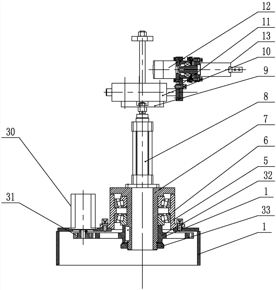
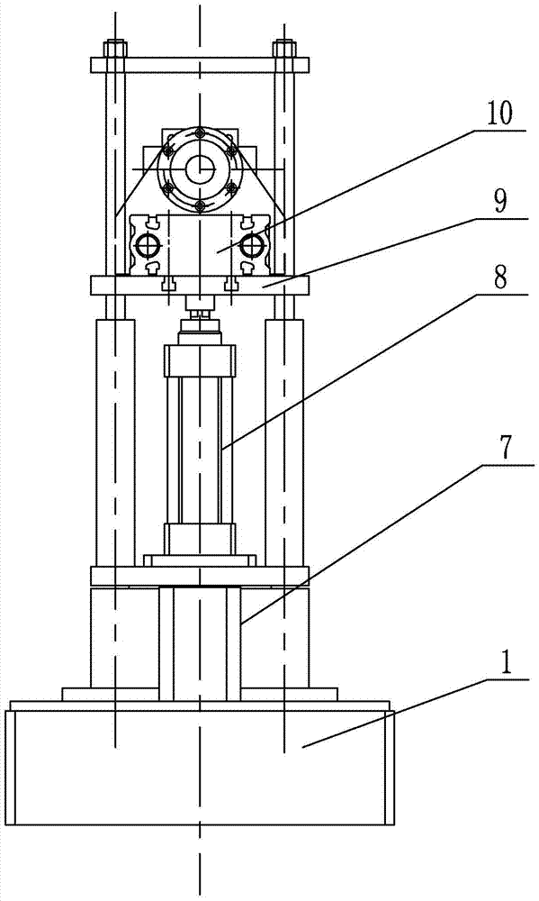
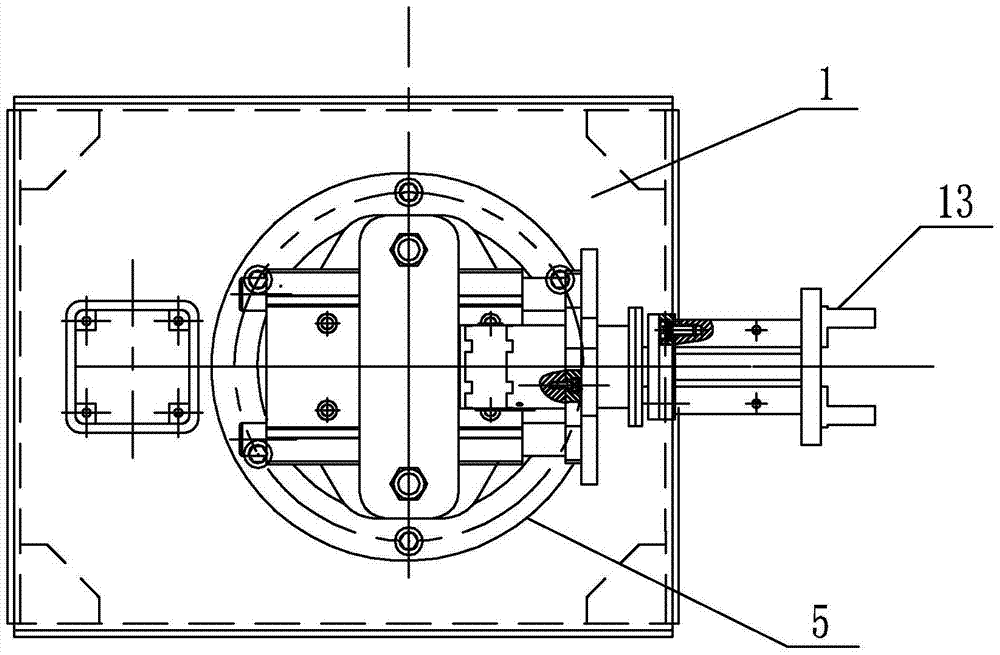
[0021] Specific implementation mode one: as Figure 1~6 As shown, the industrial robot for gear processing in this embodiment includes a bottom. The industrial robot includes a base 1, a spindle drive device 2, a spindle bearing seat 5, a rotating spindle 7, a lifting cylinder 8, an arm cylinder 10, and an arm transition plate 11. , wrist portion 12, pneumatic gripper 13 and two main shaft bearings 6, the main shaft bearing seat 5 is fixed on the upper end surface of the base 1, the rotating main shaft 7 is vertically installed on the main shaft bearing seat 5 through the two main shaft bearings 6, the main shaft The driving device 2 drives the rotating main shaft 7 to rotate, the cylinder body of the lifting cylinder 8 is fixed on the upper end surface of the rotating main shaft 7, the cylinder body of the arm cylinder 10 is fixed on the upper end surface of the piston rod of the lifting cylinder 8, and the wrist part 12 passes through the arm. The transition plate 11 is inst...

specific Embodiment approach 2

[0028] Specific implementation mode two: as figure 1 As shown, the main shaft driving device 2 of this embodiment includes a second stepping motor 30, a pinion 31, a bull gear 32 and a ring nut 33, the second stepping motor 30 is fixed on the upper end surface of the base 1, and the pinion 31 is fixed on the upper end surface of the base 1. Set on the output shaft of the second stepping motor 30, the bull gear 32 is fixedly sleeved on the bottom of the rotating main shaft 7, the ring nut 33 is threaded on the lower end of the rotating main shaft 7, and the pinion 31 and the bull gear 32 mesh with each other. Such a design can ensure high transmission precision and large transmission torque, and can ensure the transmission torque of mechanisms such as robot arms and grippers. Other components and connections are the same as those in the first embodiment.

specific Embodiment approach 3

[0029] Specific Embodiment Three: In this embodiment, the main shaft driving device 2 is a geared motor, and the geared motor is installed on the lower end surface of the panel of the base 1, and the lower end of the output shaft of the geared motor to rotate the main shaft 7 is affixed. Such a design can lower the overall center of gravity of the robot and enhance its stability. Other components and connections are the same as those in the first embodiment.


PUM


Abstract

The invention provides an industrial robot for gear machining and relates to an industrial robot. The industrial robot for gear machining solves the problems of low machining efficiency and low machining accuracy of manual operations adopted for existing machining in steps of tooth profile chamfering and deburring. A main shaft bearing block is fixedly mounted on an upper end face of a base; a rotating main shaft is vertically mounted on the main shaft bearing block through a main shaft bearing; a main shaft driving device drives the rotating main shaft to rotate; a cylinder block of a lifting cylinder is fixedly mounted on an upper end face of the rotating main shaft; a cylinder block of an arm cylinder is fixedly mounted on an upper end face of a piston rod of the lifting cylinder; a wrist portion is mounted on a piston rod of an arm cylinder through an arm transition plate and a gripper is connected to the wrist portion; a gripper rotating shaft is horizontally mounted in a bearing block assembly through a self-aligning ball bearing; and one end of the gripper rotating shaft is fixedly connected with an output shaft of a first stepping motor through a coupling, while the other end of the gripper rotating shaft is connected with a pneumatic gripper. The industrial robot for gear machining is applicable to tooth profile chamfering and deburring in gear machining.

Description

technical field [0001] The invention relates to an industrial robot, in particular to an industrial robot used for gear processing. Background technique [0002] Gears are widely used in the machinery industry, especially in the fields of automobiles and heavy machinery, where continuous meshing of gears can transmit motion and power. With the continuous improvement of the level of industrialization, my country's gear industry has developed rapidly, and the scale of the industry has continued to expand. The latest data on gear production from the National Bureau of Statistics shows that in recent years, the total output value of my country's gear industry has been on the rise year by year. In 2013, the total output value of my country's gears reached 178 billion yuan. From 2002 to 2013, the total The average annual growth rate of the output value exceeds 20%. With the rapid development of my country's economy, especially the continuous improvement of the industrial level, un...

Claims


Application Information

Patent Timeline
IPC IPC(8): B23Q7/04B25J11/00
CPCB23Q7/046B25J11/006
Inventor 王少纯
Owner HARBIN INST OF TECH
Why Eureka
Try Eureka