Aluminum product machining equipment

A processing equipment, aluminum technology, applied in the field of aluminum processing equipment

Inactive Publication Date: 2016-03-30
成都金科达铝业有限公司
View PDF6 Cites 5 Cited by
  • Summary
  • Abstract
  • Description
  • Claims
  • Application Information

AI Technical Summary

Problems solved by technology

[0004] Aiming at the above-mentioned problem that further optimizing the structure of the existing wire drawing equipment will undoubtedly play a positive role in promoting the surface wire drawing treatment, the present invention provides an aluminum material processing equipment

Method used


Image

  • Aluminum product machining equipment
  • Aluminum product machining equipment

Examples


Embodiment 1

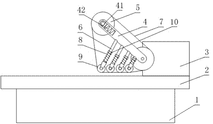
[0022] Such as figure 1 and figure 2 As shown, the aluminum material processing equipment includes a machine base 1 on which a workbench 2 and a driving part 3 are arranged, and also includes two main pulleys 5, one of which is connected to the driving part 3 On the other hand, the other main pulley 5 is connected with the machine base 1 through the first pulley rod 4, and the two main pulleys 5 are wound with a grinding belt 7, and also include a secondary pulley 9, a spring 8, a deformation adjustment part 10 and the second pulley rod 6, the second pulley rod 6 is fixedly connected to the first pulley rod 4 or the base 1, and one end of the spring 8 is sleeved on the second pulley rod 6, the deformation The adjusting part 10 is arranged on the second pulley rod 6, and one end of the spring 8 sleeved on the second pulley rod 6 is in contact with the deformation adjusting part 10. During the operation of the deformation adjusting part 10, the spring 8 is sleeved on the One ...

Embodiment 2

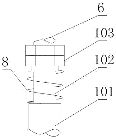
[0026] Such as figure 1 and figure 2 As shown, this embodiment is further limited on the basis of Embodiment 1: as a specific technical solution to achieve the above invention, it also includes a sleeve 101 hingedly connected to the secondary pulley 9 wheel shaft, the second belt The wheel rod 6 is also provided with a threaded segment, and the deformation adjusting part 10 is two nuts 103 threaded on the above threaded segment, and one end of the second pulley rod 6 is connected to the first pulley rod 4, the second pulley rod 6 is also provided with a guide rod segment 102 between the deformation adjustment part 10 and the free end of the second pulley rod 6, the sleeve 101 is clearance fit with the guide rod segment 102, and the spring 8 is sheathed on the guide rod section 102, and the two ends of the spring 8 are respectively in contact with the deformation adjusting part 10 and the ends of the guide rod section 102. The above two threads can be fixed on the second pul...

Embodiment 3

[0030] Such as figure 1 and figure 2 As shown, this embodiment is further limited on the basis of any one of the technical solutions provided by the above embodiments: in the above structure, the workbench 2 is used to place the workpiece, and in order to facilitate the position adjustment of the workpiece, there is also a A position adjustment unit is provided, the output end of the position adjustment unit is connected with the workbench 2 to adjust the position of the workbench 2 in the three directions of X, Y and Z, and the three directions of X, Y and Z are respectively connected with the space Cartesian coordinate system Different directions among the three directions.

[0031] A specific embodiment of the seat that facilitates the position adjustment of the workpiece, the position adjustment component in the position adjustment part is a threaded rod.


PUM


Abstract

The invention discloses aluminum product machining equipment which comprises a machine base. The machine base is provided with a working table and a driving part. The aluminum product machining equipment further comprises two main belt pulleys, and a grinding belt winds across the two main belt pulleys. The aluminum product machining equipment also comprises auxiliary belt pulleys, springs, deformation adjusting parts and second belt pulley rods. In the acting process of the deformation adjusting parts, the end, arranged on the corresponding second belt pulley rod in a sleeving mode, of each spring is adjustable in position in the length direction of the second belt pulley rod, and each auxiliary belt pulley is fixed to the other end of the corresponding spring. The side faces of the auxiliary belt pulleys make contact with the side face of the grinding belt, the axes of the auxiliary belt pulleys and the axes of the main belt pulleys are parallel, and the distance between each auxiliary belt pulley and the working table is smaller than the distance between each main belt pulley and the working table. The axes of the springs intersect with the table top of the working table. A first belt pulley rod is further provided with an adjusting groove, and a compression spring is arranged in the adjusting groove. According to the aluminum product machining equipment, reliance of work of drawing equipment on real-time manual control can be weakened, and the aluminum product machining equipment is suitable for carrying out drawing machining on aluminum plates with poor surface quality.

Description

technical field [0001] The invention relates to the field of aluminum material processing equipment, in particular to an aluminum material processing equipment. Background technique [0002] Surface brushing treatment is a surface treatment method that forms lines on the surface of the workpiece by grinding products to achieve a decorative effect. Brushed treatment can make the metal surface obtain a non-mirror-like metallic luster, which has a very strong decorative effect like silk satin, as if giving new vitality and life to ordinary metals, so the brushed treatment has more and more market recognition and Widely used, in the construction industry, there are elevator door panels, escalator decorative panels, faucets, hinges, handles, lock panels, etc. in the construction hardware industry; kitchen utensils such as range hoods, stainless steel stoves, sinks, etc. The various 3C digital products that have emerged in recent years have pushed the application of drawing to a ...

Claims


Application Information

Patent Timeline
Patent Type & Authority Applications(China)
IPC IPC(8): B24B21/14B24B21/20
CPCB24B21/14B24B21/20
Inventor 吕岩中
Owner 成都金科达铝业有限公司
Why Eureka
Try Eureka