Die for vulcanization of watertight connector

A watertight connector and mold technology, which is applied in the field of vulcanization molds for watertight connectors, can solve the problems of increased demoulding force of the filling hole, tearing of the surface of the vulcanized layer, troublesome operation process, etc. Uniform thickness and easy disassembly

Active Publication Date: 2016-03-30
HUNAN HAIDUN OPTICAL FIBER SENSING TECH ENG LAB
View PDF4 Cites 3 Cited by
  • Summary
  • Abstract
  • Description
  • Claims
  • Application Information

AI Technical Summary

Problems solved by technology

[0002] At present, the vulcanization device used for underwater optical cables or sonar system watertight connectors usually uses two materials, one is PVC material, this kind of mold is disposable, the cost is high, and it is not suitable for use in occasions that require batch vulcanization; The second is to use light metal materials, which can be reused. Generally, a two-layer structure is adopted, namely the upper mold and the lower mold. After the mold is fixed, the mold must be rotated 90° so that the glue filling port is facing upwards to vulcanize. After vulcanization, the mold needs to be restored to the original position for demoulding. This operation process is more troublesome, and it cannot be used for some special occasions. When the watertight connector is rotated, it cannot be vulcanized. At the same time, due to the existence of the glue filling hole during the demoulding process, the demoulding force near the glue filling hole will increase, resulting in uneven demoulding and tearing on the surface of the vulcanized layer. crack

Method used


Image

  • Die for vulcanization of watertight connector
  • Die for vulcanization of watertight connector

Examples


Embodiment Construction

[0013] The present invention will be further described below in conjunction with the accompanying drawings and specific embodiments.

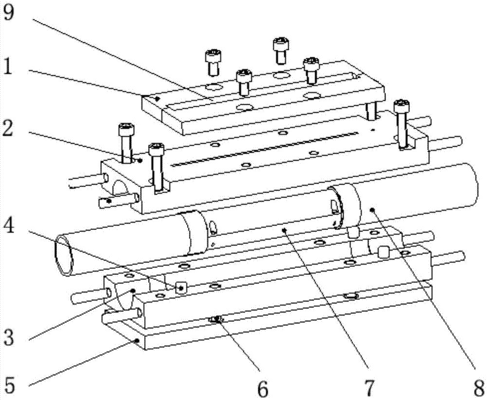
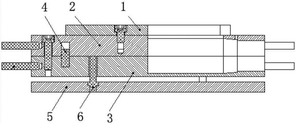
[0014] Such as figure 1 As shown, a mold for watertight connector vulcanization includes an upper mold 2, a lower mold 3 and a positioning pin 4, and the upper mold 2 and the lower mold 3 are mutually positioned by the positioning pin 4, and the upper mold 2 and the lower mold 3 After the combination, a vulcanized inner cavity matching the size of the watertight connector 7 is formed inside, and the two ends of the upper mold 2 and the lower mold 3 are provided with positioning holes for positioning the two ends of the watertight connector 7 along the central axis of the vulcanized inner cavity. hole, such as figure 1 As shown, both ends of the watertight connector 7 are covered with a PU tube 8, the PU tube 8 is a flexible material, and the outer diameter of the PU tube 8 is consistent with the inner diameter of the positioning hole formed af...


PUM


Abstract

The invention discloses a die for vulcanization of a watertight connector. The die comprises an upper die, a lower die, locating pins, a flow guide plate, a die release plate, ejector rods and a die opening rod. A whole set of vulcanization device is made of light metal materials. The upper die and the lower die are assembled for accurately positioning the watertight connector, an inner vulcanization cavity is formed, and it is ensured that the vulcanization thickness of the outer surface of the watertight connector is kept consistent. The flow guide plate is designed to be of a movable structure and is formed by combining two plates, a V-shaped flow guide groove can be formed by the flow guide plate, the flow guide plate is also demounted conveniently, and feeder removal is achieved. The locating pins are asymmetrically distributed, and cooperation accuracy can be improved. The die opening rod and the die release plate are combined to form a die release mechanism, so that the upper die and the lower die can be conveniently disengaged perpendicularly, and a vulcanization surface cannot be torn. The vulcanization device has the beneficial effects of being high in casting speed, even in vulcanization layer thickness, good in vulcanization surface quality, capable of facilitating die release and being used repeatedly, easy to operate and the like.

Description

technical field [0001] The invention relates to a mold for watertight connector vulcanization. technical background [0002] At present, the vulcanization device used for underwater optical cables or sonar system watertight connectors usually uses two materials, one is PVC material, this kind of mold is disposable, the cost is high, and it is not suitable for use in occasions that require batch vulcanization; The second is to use light metal materials, which can be reused. Generally, a two-layer structure is adopted, namely the upper mold and the lower mold. After the mold is fixed, the mold must be rotated 90° so that the glue filling port is facing upwards to vulcanize. After vulcanization, the mold needs to be restored to the original position for demoulding. This operation process is more troublesome, and it cannot be used for some special occasions. When the watertight connector is rotated, it cannot be vulcanized. At the same time, due to the existence of the glue fil...

Claims


Application Information

Patent Timeline
Patent Type & Authority Applications(China)
IPC IPC(8): B29C33/30B29C33/44
CPCB29C33/30B29C33/44
Inventor 陶光勇赵散梅向继方李友如顾兴王建夏凡
Owner HUNAN HAIDUN OPTICAL FIBER SENSING TECH ENG LAB
Why Eureka
Try Eureka