
Pressure-free buffer platform
A buffer platform and pressure technology, applied in the direction of conveyor objects, transportation and packaging, can solve the problems of not being able to squeeze, crooked bottles and pouring bottles, etc., to achieve the effect of reducing squeezing and taking up less space
- Summary
- Abstract
- Description
- Claims
- Application Information
AI Technical Summary
Problems solved by technology
Method used
Image

Examples
Embodiment Construction
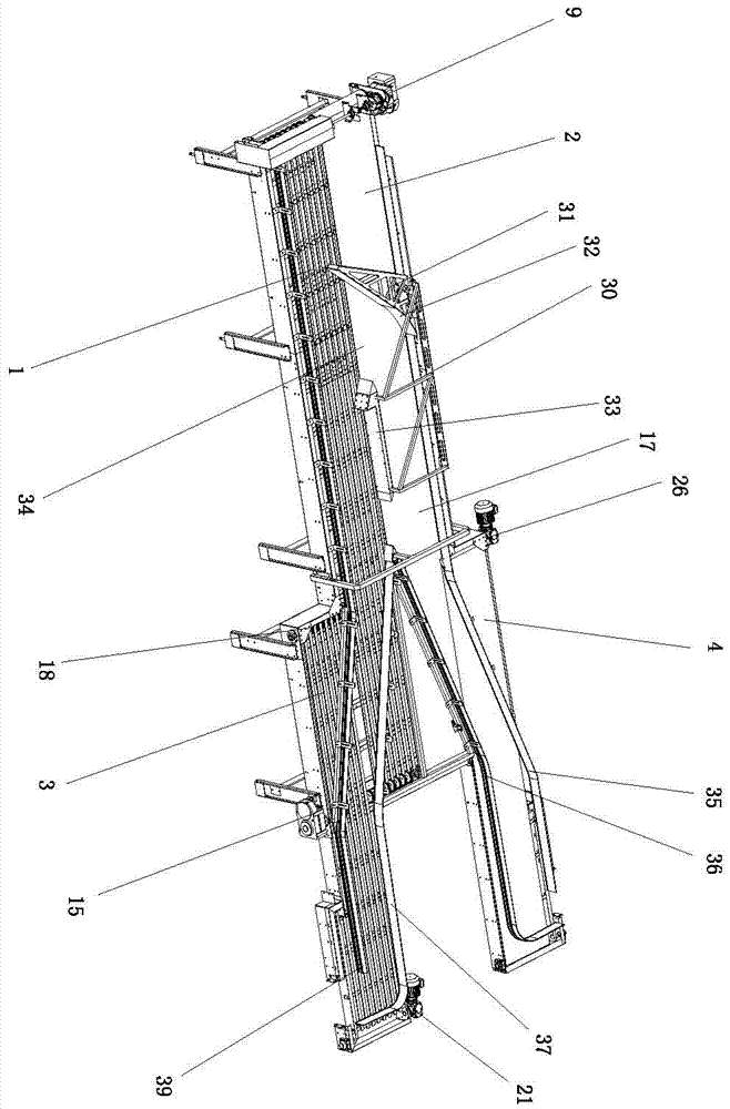
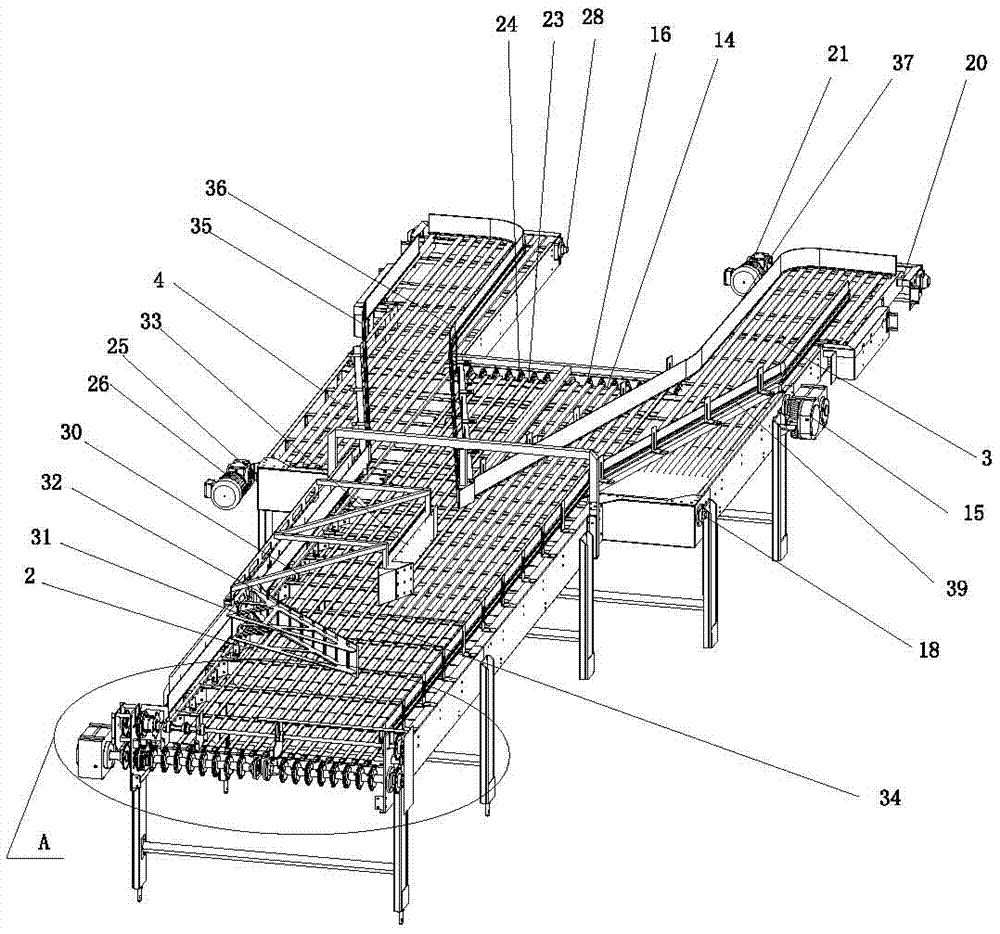
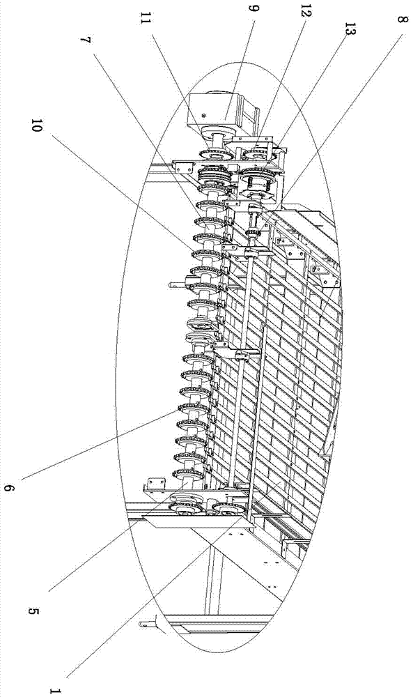
[0014] Depend on Figure 1 to Figure 3 As shown, the present invention includes a first buffer platform frame body 1, a second buffer platform frame body 2, a third buffer platform frame body 3, a fourth buffer platform frame body 4 and a guide device, and the first buffer platform frame body 1 Set side by side with the second buffer platform frame 2, the third buffer platform frame 3 is located near the rear end of the first buffer platform frame 1, and the fourth buffer platform frame 4 is located near the second buffer platform frame At the rear end position of the body 2, a first rotating shaft 5 is provided on the front end of the first buffer platform frame body 1, a first rotating gear 6 is provided on the first rotating shaft 5, and a first rotating gear 6 is arranged on the front end of the second buffer platform frame body 2. The second rotating shaft 7, the third rotating shaft 8 and the first rotating motor 9 connected with the second rotating shaft 7 are provided ...
PUM
 Abstract
Description
Claims
Application Information