Pneumatic feeding device

A feeding device and feeding technology, applied in the direction of transportation and packaging, conveyors, conveyor objects, etc., can solve the problems of short service life, troublesome spring replacement, and easy damage of springs, so as to improve work efficiency and facilitate processing effect of effect

Inactive Publication Date: 2016-03-30
CHONGQING XIUCAI BAY FRUIT & VEGETABLE PROFESSIONAL COOP
View PDF0 Cites 2 Cited by
  • Summary
  • Abstract
  • Description
  • Claims
  • Application Information

AI Technical Summary

Problems solved by technology

[0002] Fruit processing requires a variety of machines, and these machines all need a feeding device to add fruit. The most commonly used feeding device in the prior art is a spring feeding device. The spring feeding device includes a feeding tube. There is a baffle, one end of the baffle is movably connected to the inner side of the feeding tube, the other end of the baffle is fixedly connected to one end of the compression spring, and the other end of the compression spring is fixedly connected to the inner side of the feeding tube, when a certain amount of fruit enters the feeding tube, press down the baffle The fruit flows in behind the plate; the spring of this spring feeding device is easily damaged, so the service life is not long. At the same time, if you need to make different amounts of fruit flow in, you need to replace the spring, but it is more troublesome to replace the spring

Method used


Image

  • Pneumatic feeding device

Examples


Embodiment Construction

[0011] The present invention will be described in further detail below by means of specific embodiments:

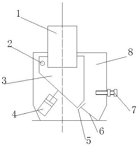
[0012] The reference signs in the drawings of the description include: observation tube 1, hinge shaft 2, rotary hopper 3, cylinder 4, baffle plate 5, support shaft 6, limit bolt 7, and feed box 8.

[0013] Such as figure 1 As shown, the pneumatic feeding device of this embodiment includes a feeding box body 8, an observation tube 1 is provided at the upper end of the feeding box body 8, and a rotating hopper 3 is provided at a position parallel to the observation tube 1, and the rotating hopper 3 includes a feed inlet and an outlet. The diameter of the feed port is greater than the diameter of the discharge port, and a slope is provided between the feed port and the discharge port. The rotary hopper 3 is located inside the feed box body 8, and the rotary hopper 3 is connected to the feed box through the hinge shaft 2. The body 8 is hinged and the rotating hopper 3 can r...


PUM


Abstract

The invention relates to the field of discharge hoppers, in particular to a pneumatic feeding device. The pneumatic feeding device comprises a feeding box body, wherein a hinge shaft is arranged in the feeding box body; an observing barrel is arranged at the upper end of the feeding box body; a rotary hopper is arranged at a position parallel to the observing barrel, is hinged to the feeding box body through the hinge shaft, is positioned in the feeding box body and is conical; a feeding opening and a discharging opening are formed in the rotary hopper; the aperture of the feeding opening is greater than that of the discharging opening; a cylinder is arranged on the left side of the bottom of the feeding box body and comprises a piston and a piston rod; the piston rod is fixedly connected with the rotary hopper; a supporting mechanism is arranged on the right side of the bottom of the feeding box body and comprises a baffle and a supporting shaft; one end of the supporting shaft is fixedly connected with the bottom of the feeding box body; the other end of the supporting shaft is fixedly connected with the baffle; a through hole is formed in the right side of the feeding box body; and a limiting bolt penetrates through the through hole and is in threaded connection with the feeding box body. According to the scheme, fruits can be quantitatively conveyed, the conveying amount of the fruits can be adjusted flexibly, and meanwhile, the pneumatic feeding device is long in service life.

Description

technical field [0001] The invention relates to the field of unloading hoppers, in particular to a pneumatic feeding device. Background technique [0002] Fruit processing requires a variety of machines, and these machines all need a feeding device to add fruit. The most commonly used feeding device in the prior art is a spring feeding device. The spring feeding device includes a feeding tube. There is a baffle, one end of the baffle is movably connected to the inner side of the feeding tube, the other end of the baffle is fixedly connected to one end of the compression spring, and the other end of the compression spring is fixedly connected to the inner side of the feeding tube, when a certain amount of fruit enters the feeding tube, press down the baffle The fruit flows in behind the plate; the spring of this spring feeding device is easily damaged, so the service life is not long. At the same time, if it is necessary to make different amounts of fruit flow in, it needs to...

Claims


Application Information

Patent Timeline
Patent Type & Authority Applications(China)
IPC IPC(8): B65G47/74
CPCB65G47/74B65G2201/0211
Inventor 袁东升
Owner CHONGQING XIUCAI BAY FRUIT & VEGETABLE PROFESSIONAL COOP
Why Eureka
Try Eureka