
Continuous bin type pneumatic conveying pump

A pneumatic conveying and conveying pump technology, which is applied in the field of continuous warehouse pneumatic conveying pumps, can solve the problems of high production cost, large pipeline wear, and small amount of conveyed materials, so as to overcome high manufacturing cost, reduce failure rate, and reduce production cost effect

Active Publication Date: 2016-03-30
ANHUI NAILIDE PNEUMATIC CONVEYING CO LTD
View PDF2 Cites 1 Cited by
  • Summary
  • Abstract
  • Description
  • Claims
  • Application Information

AI Technical Summary

Problems solved by technology

[0003] However, the existing traditional warehouse-type pneumatic conveying generally adopts the intermittent conveying method, that is, each conveying of traditional pneumatic conveying is divided into three processes: 1. The climbing process, we set the time as t 1 , in this period, the mixing ratio is low, the gas consumption is large, and the energy consumption is high; 2. The stable transportation process, the time is t 2 At this time, the mixing ratio of conveyed materials reaches the optimum value, the conveying volume is the largest, the speed is low, and the wear on the conveying pipeline is small. It is the best state of pneumatic conveying, and it is also the best conveying state that people pursue; process), the time is t 3 , this period is used to blow out the material in the pipe, the air source is in a short-circuit state, and the air consumption is the largest
The current pneumatic conveying method cannot realize the continuous conveying of materials, and has the disadvantages of small amount of conveyed materials, large pipeline wear, large air consumption, low efficiency, and high production costs.

Method used


Image

  • Continuous bin type pneumatic conveying pump
  • Continuous bin type pneumatic conveying pump
  • Continuous bin type pneumatic conveying pump

Examples


Embodiment Construction

[0037] The following will clearly and completely describe the technical solutions in the embodiments of the present invention with reference to the drawings in the embodiments of the present invention. Based on the embodiments of the present invention, all other embodiments obtained by persons of ordinary skill in the art without making creative efforts belong to the protection scope of the present invention.

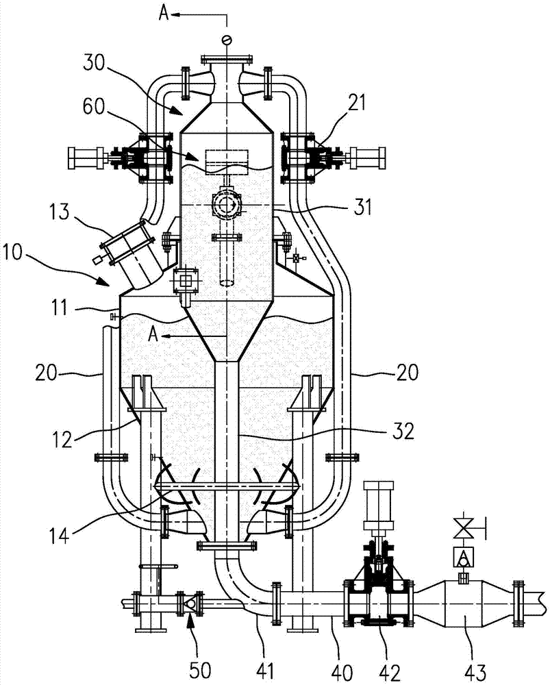
[0038] Such as figure 1 As shown, the conveying pump includes a storage transfer bin 10, a transfer pipe 20, a transfer bin 30, a discharge pipeline 40, and also includes a pneumatic pressure feeding device 60 and an air supply pipeline 50. The volume of the storage transfer bin 10 is greater than The volume of the delivery bin 30. Each component will be described separately below.

[0039] 1. Material storage transfer bin 10

[0040] Such as figure 1 As shown, the material storage transfer bin 10 includes a cylindrical upper transfer bin 11 and an inverted conical ...


PUM


Abstract

The invention belongs to the technical field of material conveying, and particularly relates to a continuous bin type pneumatic conveying pump capable of continuously achieving material conveying. The conveying pump comprises an intermittent-working storage material conveying bin and a continuous-working conveying bin. A feeding opening is formed in the upper side of the storage material conveying bin, the volume of the storage material conveying bin is larger than that of the conveying bin, and the conveying bin is inserted in the storage material conveying bin from top to bottom. A plurality of conveying pipes connecting the storage material conveying bin with the conveying bin and conveying powder are arranged between the storage material conveying bin and the conveying bin. The continuous bin type pneumatic conveying pump further comprises a pneumatic pressure feed device supplying air to the storage material conveying bin and the conveying bin, and a discharging device is arranged at a bottom outlet of the conveying bin. According to the continuous bin type pneumatic conveying pump, continuous material conveying can be achieved, accordingly, the conveying efficiency is improved, the conveying pipeline abrasion is reduced, the production efficiency is improved, and time cost is reduced. Meanwhile, the equipment manufacturing cost can be saved, the equipment occupied area is reduced, the functions of saving energy and reducing consumption are achieved, and the defects that the equipment manufacturing cost is high, and assembling is difficult are overcome.

Description

technical field [0001] The invention belongs to the technical field of material conveying, and in particular relates to a continuous chamber type pneumatic conveying pump which can continuously realize material conveying. Background technique [0002] Pneumatic conveying uses the energy of airflow to transport powdery and granular materials along the direction of airflow in a closed pipeline, which is a specific application of fluidization technology. The pneumatic conveying device has a simple structure and is easy to operate. It can be used for horizontal, vertical or inclined conveying. During the conveying process, it can also perform physical operations such as heating, cooling, drying and air classification of materials or certain chemical operations. The main features of pneumatic conveying are large conveying capacity, long conveying distance and high conveying speed; it can be loaded in one place and then unloaded in multiple places. Due to these characteristics of...

Claims


Application Information

Patent Timeline
IPC IPC(8): B65G53/50B65G53/16
CPCB65G53/16B65G53/50B65G2201/04
Inventor 许晓慧贾功勋葛茯苓
Owner ANHUI NAILIDE PNEUMATIC CONVEYING CO LTD
Learn More