Light control pneumatic exhaust window

A technology for lighting control and smoke exhaust windows, which is applied in door/window accessories, power control mechanisms, buildings, etc., to achieve the effect of being suitable for large-scale industrial production and solving the problem of automatic opening and closing.

Active Publication Date: 2016-03-30
TIANJIN LIAN JILONG DOOR & WINDOW
View PDF10 Cites 1 Cited by
  • Summary
  • Abstract
  • Description
  • Claims
  • Application Information

AI Technical Summary

Problems solved by technology

However, this pneumatic smoke exhaust window still has a lot of shortcomings in terms of automatic control.

Method used


Image

  • Light control pneumatic exhaust window
  • Light control pneumatic exhaust window
  • Light control pneumatic exhaust window

Examples


Embodiment Construction

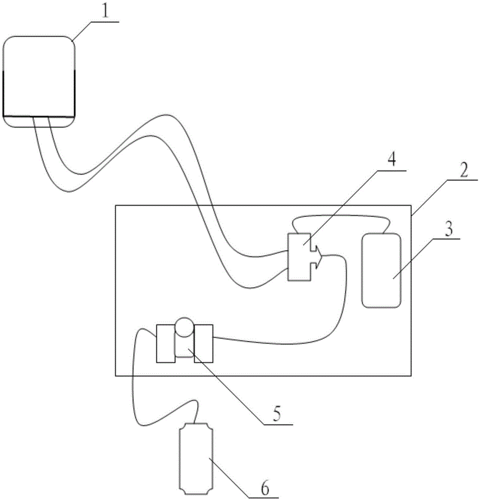
[0022] For further illustrating the present invention, now cooperate with accompanying drawing to elaborate:

[0023] Such as Figure 1-4 As shown, the light control pneumatic smoke exhaust window includes a pneumatic smoke exhaust window 1, an air pump 6, a box body 2, a light induction control box 3 arranged in the box body 2, a pneumatic solenoid valve 4 and a gas-water separator 5. The pneumatic solenoid valve is a three-way structure, the outlet at one end is connected to the pipeline of the gas-water separator, and the outlet at the other two ends is connected to the pipeline of the sliding support part of the pneumatic smoke exhaust window (one of the ports pumps out gas using the sliding support part Push open the window, the other port sucks in gas and closes the window by sliding support parts), the air pump is connected with the gas-water separator pipeline, the light induction control box is connected with the pneumatic solenoid valve circuit, and at the same time,...


PUM


Abstract

The invention provides a light control pneumatic exhaust window. The light control pneumatic exhaust window comprises a pneumatic exhaust window body, an air pump, a tank, a light induction control box, a pneumatic electromagnetic valve and a gas-water separator, wherein the light induction control box, the pneumatic electromagnetic valve and the gas-water separator are arranged inside the tank; the pneumatic electromagnetic valve is of a tee-joint structure, an outlet in one end of the pneumatic electromagnetic valve is connected with the gas-water separator through a pipeline, and outlets in the other two ends of the pneumatic electromagnetic valve are connected with a sliding supporting component of the pneumatic exhaust window body through pipelines; the air pump is connected with the gas-water separator through a pipeline; the light induction control box is connected with the pneumatic electromagnetic valve through a circuit and connected with a control button on the tank through a circuit. Through the ingenious design of the light induction control box, the pneumatic electromagnetic valve is operated and controlled in real time and then cooperates with pneumatic equipment to control opening and closing of the pneumatic window, so that automatic opening and closing control after the pneumatic exhaust window and a fire control system are connected is well achieved, and the demands of large-scale industrial production are met.

Description

technical field [0001] The invention relates to the field of smoke exhaust window production, in particular to an illumination control pneumatic smoke exhaust window. Background technique [0002] Around 2000, the pneumatic smoke exhaust window technology was introduced into China. After more than ten years of development, the pneumatic smoke exhaust window technology has further matured. By 2010, the pneumatic smoke exhaust window has eroded about 20% of the market share of the mechanical most dynamic smoke exhaust window, and its development is rapid, mainly because the pneumatic smoke exhaust window can be used for daily ventilation, air conditioning, and lighting. Fire-fighting and smoke exhaust and other functions, and the installation is simpler than electric smoke exhaust windows, the maintenance rate is low, energy saving and environmental protection. [0003] The invention with the application number of 201320085537.3 discloses a pneumatic smoke exhaust window, whi...

Claims


Application Information

Patent Timeline
Patent Type & Authority Applications(China)
IPC IPC(8): E05F15/20E05F15/02
Inventor 郑大吉
Owner TIANJIN LIAN JILONG DOOR & WINDOW
Why Eureka
Try Eureka