Refrigeration system and control method thereof

A refrigeration system and control valve technology, which is applied in the field of air conditioning, can solve the problems that the unit cannot be started, cannot operate refrigeration, cannot guarantee the unit to start and operate reliably, and achieve the effect of easy control, implementation and reliable operation

Active Publication Date: 2016-03-30
GD MIDEA HEATING & VENTILATING EQUIP CO LTD +1
View PDF8 Cites 24 Cited by
  • Summary
  • Abstract
  • Description
  • Claims
  • Application Information

AI Technical Summary

Problems solved by technology

In areas with higher latitudes, the outdoor temperature is very low in winter, and the air conditioner in the computer room still needs cooling at this time. At this time, for the general cooling system design, the unit may not be able to start and cannot run the cooling system.
Although some computer room air conditioners in the prior art can solve the problem of low-temperature start-up and operation, their application range is relatively narrow, and they can only be started and run at -35°C. Ambient temperature, there is no guarantee that the unit can start and operate reliably

Method used


Image

  • Refrigeration system and control method thereof
  • Refrigeration system and control method thereof
  • Refrigeration system and control method thereof

Examples


Embodiment 1

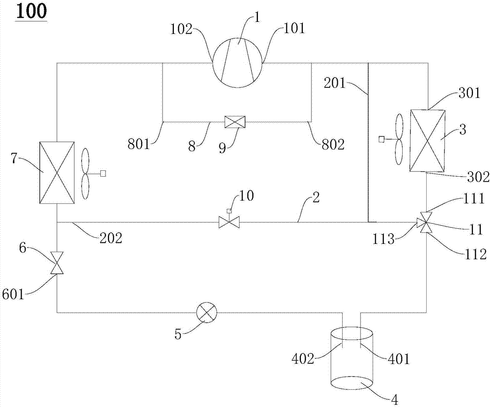
[0042] Such as figure 1 As shown, in this embodiment, the refrigeration system 100 includes a compressor 1 , a condenser 3 , a throttling device 6 , an evaporator 7 , a bypass circuit 2 and a control valve group connected end to end in order to form a circuit. The connection relationship of the above-mentioned components in the refrigeration system 100 has been described above, and will not be repeated here.

[0043] Further, the refrigeration system 100 also includes a liquid accumulator 4 and a dry filter 5 . The reservoir 4 has a reservoir inlet 401 and a reservoir outlet 402, the reservoir inlet 401 is connected to the outlet 302 of the condenser 3, the reservoir outlet 402 is connected to the inlet 601 of the throttling device 6, and the dry filter 5 It is connected in series between the outlet 402 of the liquid reservoir and the inlet 601 of the throttling device 6 . Thus, the refrigerant flowing out from the condenser 3 can flow into the accumulator 4 through the accu...

Embodiment 2

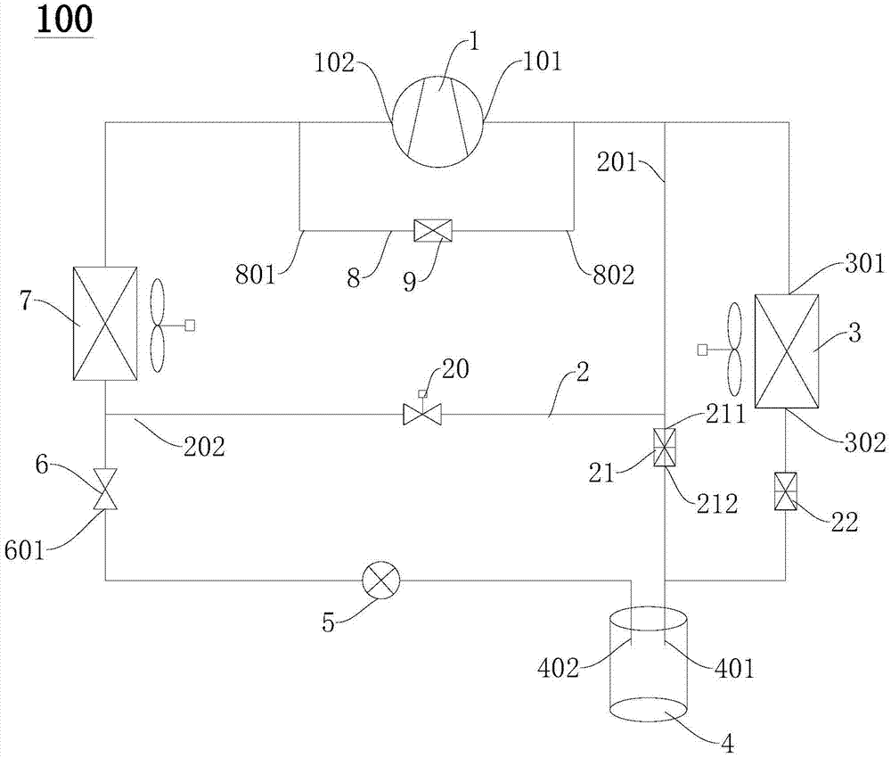
[0062] Such as figure 2 As shown, the structure of the refrigeration system 100 in this embodiment is substantially the same as that of the first embodiment above, and the only difference lies in the structure of the control valve group.

[0063]Specifically, the control valve group in this embodiment includes a second solenoid valve 20 , a differential pressure valve 21 and a condensing pressure regulating valve 22 . The second solenoid valve 20 is arranged on the bypass circuit 2, and the second solenoid valve 20 is configured to conduct the bypass circuit 2 when the suction pressure of the compressor 1 is lower than a third predetermined value and when the suction pressure of the compressor 1 When the pressure is higher than or equal to the third predetermined value, the bypass circuit 2 is cut off.

[0064] The first end 211 of the differential pressure valve 21 is connected between the first end 201 of the bypass circuit 2 and the second solenoid valve 20 , and the seco...

Embodiment 3

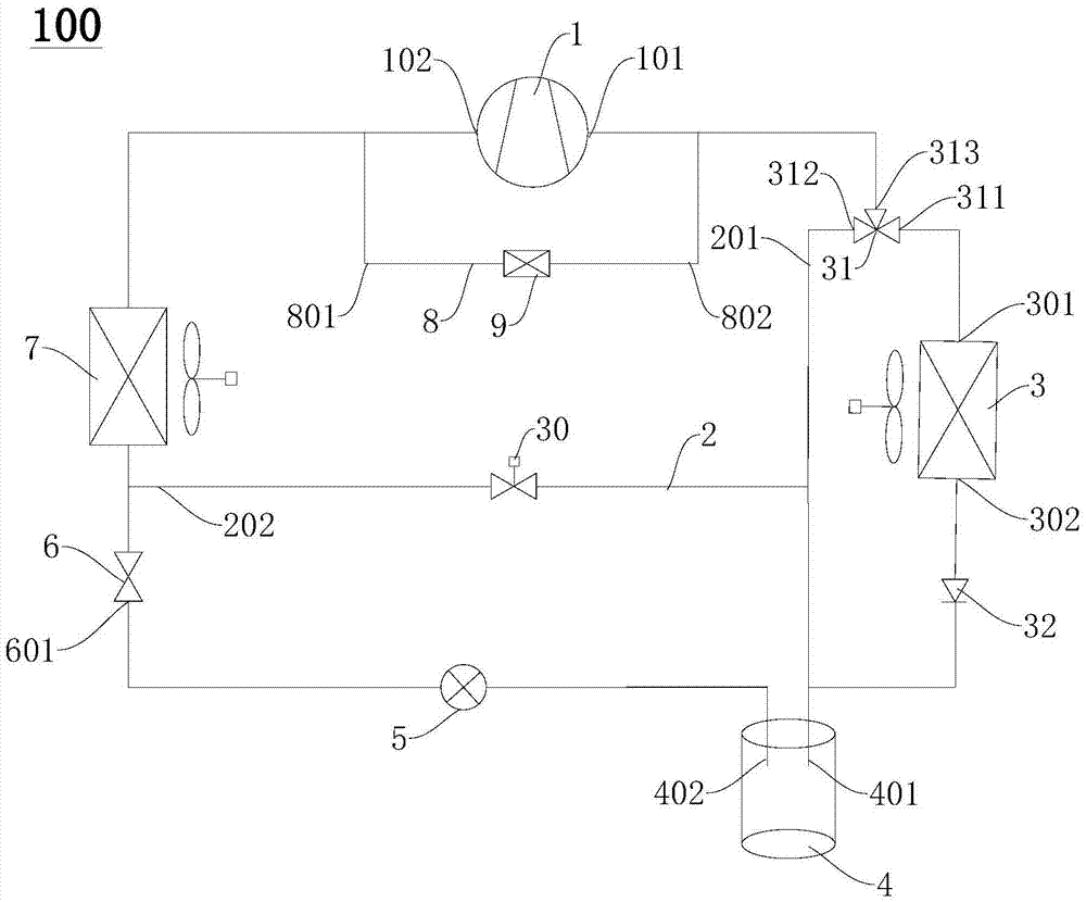
[0073] Such as image 3 As shown, the structure of the refrigeration system 100 in this embodiment is substantially the same as that in the first embodiment above, and the only difference lies in the structure of the control valve group.

[0074] The control valve group in this embodiment includes a third solenoid valve 30 and a second pressure three-way valve 31 . The third solenoid valve 30 is arranged on the bypass circuit 2, and the third solenoid valve 30 is configured to conduct the bypass circuit 2 when the suction pressure of the compressor 1 is lower than the sixth predetermined value and when the suction pressure of the compressor 1 When the pressure is higher than or equal to the sixth predetermined value, the bypass circuit 2 is cut off. The first valve port 311 of the second pressure three-way valve 31 is connected to the exhaust port 101 of the compressor 1, and the second valve port 312 of the second pressure three-way valve 31 is connected to the first end 201...


PUM


Abstract

The invention discloses a refrigeration system and a control method thereof. The refrigeration system comprises a compressor, a condenser, a throttle device and an evaporator which are connected end to end in sequence to form a loop, a bypass loop and a control valve group, wherein a first end of the bypass loop is connected between an exhaust port of the compressor, and the condenser, and a second end of the bypass loop is connected between the throttle device and the evaporator; and the control valve group is used for controlling exhaust gas of the compressor to selectively flow through one of the bypass loop and the condenser. The refrigeration system disclosed by the invention can be preheated through the arranged bypass loop to normally start, and the exhaust gas of the compressor can be controlled to selectively flow through one of the bypass loop and the condenser through the control valve group according to an external environment temperature, thus the refrigeration system is enabled to start in a low-temperature environment, and run stably and reliably.

Description

technical field [0001] The invention relates to the technical field of air conditioning, in particular to a refrigeration system and a control method thereof. Background technique [0002] In related technologies, the computer room air conditioner is a special series of air conditioners that require safe and reliable operation around the clock. In areas with higher latitudes, the outdoor temperature is very low in winter, and the computer room air conditioner still needs cooling at this time. At this time, for the general cooling system design, the unit may not be able to start and cannot run cooling. Although some computer room air conditioners in the prior art can solve the problem of low-temperature start-up and operation, their application range is relatively narrow, and they can only be started and run at -35°C. The ambient temperature cannot guarantee that the unit can start and operate reliably. Contents of the invention [0003] The present invention aims to solv...

Claims


Application Information

Patent Timeline
Patent Type & Authority Applications(China)
IPC IPC(8): F25B1/00F25B41/04F25B49/02F25B41/20
CPCF25B1/00F25B49/022F25B2400/0401F25B2700/21F25B2500/31F25B2600/02F25B41/20
Inventor 不公告发明人
Owner GD MIDEA HEATING & VENTILATING EQUIP CO LTD
Why Eureka
Try Eureka