
Thermoelectric refrigerating unit and method for improving refrigerating efficiency of thermoelectric refrigerating unit

A technology of thermoelectric cooler and hot arm, which is applied to the operation mode of the machine, refrigerator, refrigeration components, etc., can solve the problems of inability to achieve the cooling efficiency of traditional refrigeration devices, small cooling temperature difference between the cold end and the hot end, and low thermoelectric conversion rate, etc. problem, to achieve the effect of improving the efficiency of thermoelectric conversion and increasing the temperature difference of refrigeration

Inactive Publication Date: 2016-03-30
HENAN UNIVERSITY OF TECHNOLOGY
View PDF6 Cites 7 Cited by
  • Summary
  • Abstract
  • Description
  • Claims
  • Application Information

AI Technical Summary

Problems solved by technology

[0003] Compared with traditional refrigerating devices, one of the disadvantages of semiconductor refrigerating devices is that the thermoelectric conversion rate is low, the cooling temperature difference between the cold end and the hot end is small, and the cooling efficiency of traditional refrigerating devices cannot be achieved.
In order to solve this problem, the usual design idea is to improve the heat conduction efficiency of the thermal arm of the semiconductor material, which brings great pressure on the research and development cost and workload

Method used


Image

  • Thermoelectric refrigerating unit and method for improving refrigerating efficiency of thermoelectric refrigerating unit
  • Thermoelectric refrigerating unit and method for improving refrigerating efficiency of thermoelectric refrigerating unit
  • Thermoelectric refrigerating unit and method for improving refrigerating efficiency of thermoelectric refrigerating unit

Examples


Embodiment Construction

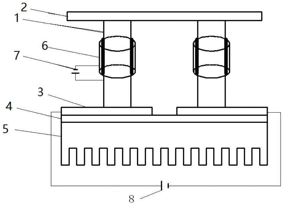
[0019] Reference attached figure 1 , showing the circuit structure of the thermoelectric refrigerator of the present invention, including a semiconductor thermal arm 1, the two ends of the semiconductor thermal arm are divided into a heat-absorbing end and a heat-dissipating end; the second DC power supply 8 provides a driving current, and the electrode 3 passes through the heat-releasing end Connection, semiconductor thermal arm 1 and heat-absorbing end electrode 2 form a loop, heat-absorbing end electrode 2 absorbs heat to become a heat-absorbing end, and exothermic end electrode 3 releases heat to form an exothermic end; heat sink 5 is connected to exothermic end electrode 3 Dissipate heat to the outside air; in order to achieve good electrical insulation and heat conduction, an insulating ceramic 4 is provided between the metal heat sink and the exothermic end electrode for isolation, and the exothermic end electrode and the insulating ceramic pass through silicone grease w...


PUM


Abstract

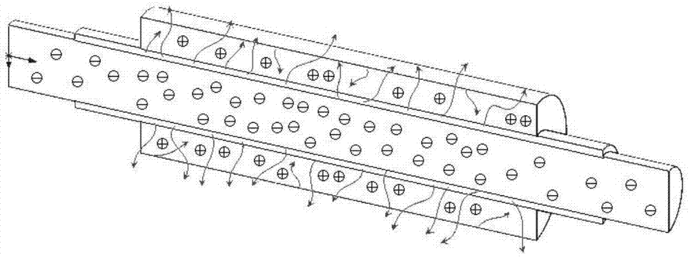
The invention discloses a thermoelectric refrigerating unit which comprises a semiconductor thermal arm and an electroluminescence body at the outer edge of the semiconductor thermal arm. A first direct-current power source is connected with the semiconductor thermal arm and the electroluminescence body to achieve luminescence refrigerating. A second direct-current power source provides drive current, and the current passes through a thermal release end electrode, the semiconductor thermal arm, a thermal absorption end electrode and the thermal release end electrode to form a loop. The thermal absorption end of the semiconductor thermal arm is connected with a thermal absorption end metal electrode, the thermal release end of the semiconductor thermal arm is connected with a thermal release end metal electrode and connected with a metal thermal sink through thermal conduction silicone grease, and the metal thermal sink carries out thermal radiation outwards. According to the thermoelectric refrigerating unit, phonons in thermoelectric materials are absorbed through electroluminescence, the reflux quantity of phonons in the thermal arm can be effectively reduced, and therefore the refrigerating efficiency of the thermoelectric refrigerating unit is improved.

Description

technical field [0001] The invention relates to a thermoelectric cooler, which belongs to the technical field of semiconductor refrigeration. Background technique [0002] Semiconductor refrigeration has been applied in miniaturized refrigeration devices because it does not require mechanical units such as compressors required by traditional refrigeration structures. Semiconductor refrigeration uses the Peltier effect of semiconductor materials. When direct current passes through a galvanic couple formed by two different semiconductor materials in series, heat can be absorbed and released at both ends of the galvanic couple to achieve the purpose of refrigeration. [0003] Compared with traditional refrigerating devices, one disadvantage of semiconductor refrigerating devices is that the thermoelectric conversion rate is low, the cooling temperature difference between the cold end and the hot end is small, and the cooling efficiency of traditional refrigerating devices canno...

Claims


Application Information

Patent Timeline
IPC IPC(8): F25B21/02F25B49/00
CPCF25B21/02F25B49/00F25B2321/021
Inventor 王赞王珂王炯全磊
Owner HENAN UNIVERSITY OF TECHNOLOGY
Learn More