
Refrigeration cycle device

A refrigeration cycle and cavity control technology, applied in refrigerators, refrigeration components, refrigeration and liquefaction, etc., can solve the problems of small applicable working conditions, low performance, and inability to effectively improve the energy efficiency of the heating system, and achieve high operating efficiency, The effect of improving heating capacity and energy efficiency

Active Publication Date: 2016-03-30
GREE ELECTRIC APPLIANCES INC +1
View PDF7 Cites 9 Cited by
  • Summary
  • Abstract
  • Description
  • Claims
  • Application Information

AI Technical Summary

Problems solved by technology

[0002] The variable capacity technology commonly used in the field of rotary hermetic compressors is to construct ordinary single-stage double cylinders or ordinary single-stage multi-cylinders to perform non-compression operation of a certain compression mechanism at low loads, so as to achieve low-performance operation and improve compression. The efficiency of the machine and its refrigeration cycle system, but the existing refrigeration cycle device that uses a variable capacity rotary hermetic compressor, the system energy efficiency improvement is applicable to a small range of conditions, and cannot effectively improve the heating capacity and low temperature under low temperature heating conditions. System energy efficiency under heating conditions

Method used


Image

  • Refrigeration cycle device
  • Refrigeration cycle device
  • Refrigeration cycle device

Examples


Embodiment 1

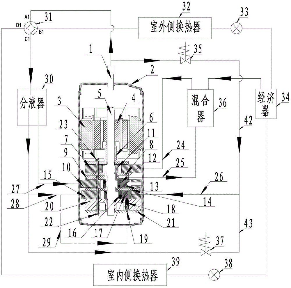
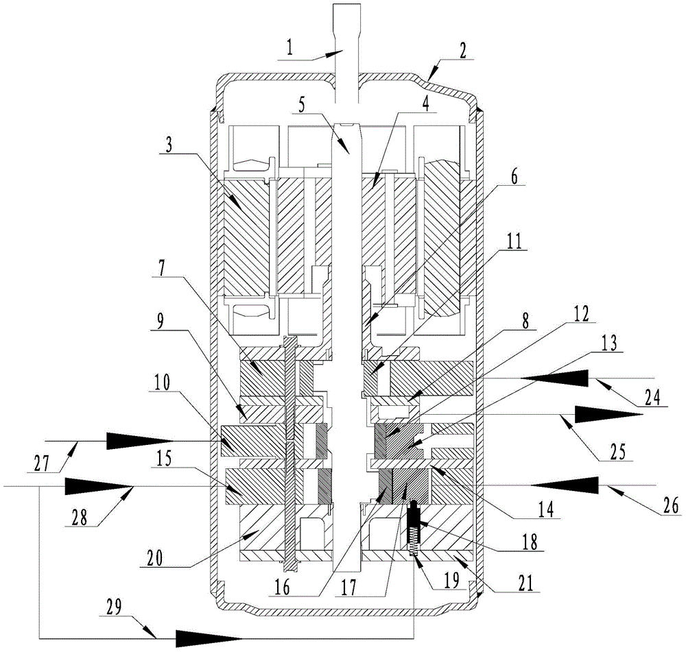
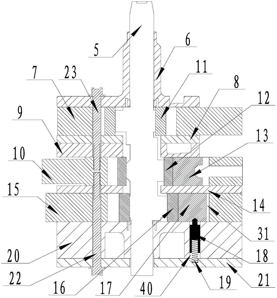
[0025] refer to Figure 1 to Figure 3 , taking a rotary compressor with one high-pressure cylinder and two low-pressure cylinders as an example to illustrate the inventive refrigeration cycle device, the compressor includes a high-pressure exhaust pipe 1, a sealed casing 2, a motor stator 3, a motor rotor 4, Crankshaft 5, upper flange 6, high-pressure cylinder 7, upper partition 8, middle partition 9, second low-pressure cylinder 10, high-pressure cylinder roller 11, second low-pressure cylinder roller 12, second low-pressure cylinder slide 13, Lower partition 14, first low-pressure cylinder 15, first low-pressure cylinder roller 16, first low-pressure cylinder slide 17, pin 18, spring 19, lower flange 20, lower flange cover 21, first screw 22, The second screw 23 .

[0026] Wherein, the first suction pipe 28 is used as the suction pipe of the first low-pressure cylinder 15, the second suction pipe 27 is used as the suction pipe of the second low-pressure cylinder 10, and the...

Embodiment 2

[0036] The main difference between Embodiment 2 and Embodiment 1 is that a three-way valve is used instead of the first electronic valve and the second electronic valve in Embodiment 1, and the first valve port of the three-way valve is connected to the high-pressure exhaust pipe of the rotary compressor. , the second valve port of the three-way valve is connected to the control chamber, and the third valve port of the three-way valve is connected to the low-pressure side of the refrigeration cycle device.

[0037] see Figure 2 to Figure 4 The first valve port A2 of the three-way valve 41 is connected to the high-pressure exhaust pipe 1, the second valve port B2 of the three-way valve 41 is connected to the intake pipe 26, and the third valve port C2 of the three-way valve 41 is connected to the refrigeration cycle device. On the low-pressure side, the third valve port C2 of the three-way valve 41 in the figure communicates with the liquid separator 30 . The communication be...


PUM


Abstract

The invention provides a refrigeration cycle device which comprises a rotary compressor, a first heat exchanger, a first throttling mechanism and a second heat exchanger, and the rotary compressor, the first heat exchanger, the first throttling mechanism and the second heat exchanger are sequentially connected to form a refrigeration cycle loop. The rotary compressor comprises at least two sets of low-pressure cylinders and at least one set of high-pressure cylinders, the low-pressure cylinders are used as first-stage compressing cylinders, the high-pressure cylinders are used as second-stage compressing cylinders, one of the at least two sets of low-pressure cylinders is provided with a pressure switching mechanism, the pressure switching mechanism comprises switch pieces, and the switch pieces are used for guiding low-pressure refrigerants or high-pressure refrigerants of the refrigeration cycle device to a control cavity arranged on the rear surface of a sliding piece in a switching mode; the pressure switching mechanism further comprises a sliding piece limiting element, and a back pressure chamber at the lower end of the sliding piece limiting element is always communicated with the low-pressure refrigerants. The refrigeration cycle device has following beneficial effects: a certain low-pressure cylinder is smoothly switched between non-compression operation and normal-compression operation to achieve improvement of energy efficiency of the refrigeration cycle device; and different displacements and different high-low-pressure-level displacement ratios are selected according to requirements for comfortableness of an air conditioner.

Description

technical field [0001] The invention relates to the refrigeration field, in particular to a refrigeration cycle device. Background technique [0002] The variable capacity technology commonly used in the field of rotary hermetic compressors is to construct ordinary single-stage double cylinders or ordinary single-stage multi-cylinders to perform non-compression operation of a certain compression mechanism at low loads, so as to achieve low-performance operation and improve compression. The efficiency of the machine and its refrigeration cycle system, but the existing refrigeration cycle device that uses a variable capacity rotary hermetic compressor, the system energy efficiency improvement is applicable to a small range of conditions, and cannot effectively improve the heating capacity and low temperature under low temperature heating conditions. System energy efficiency under heating conditions. Contents of the invention [0003] In view of the status quo of the prior a...

Claims


Application Information

Patent Timeline
Patent Type & Authority Applications(China)
IPC IPC(8): F25B41/00F25B41/40
Inventor 罗惠芳魏会军吴健杨欧翔徐嘉梁社兵邹鹏王相
Owner GREE ELECTRIC APPLIANCES INC
Learn More