Eureka AIR delivers breakthrough ideas for toughest innovation challenges, trusted by R&D personnel around the world.

Vacuumizing device and operation method using vacuumizing device

A technology for vacuuming devices and operating methods, which is applied to valve devices, sliding valves, instruments, etc., can solve the problems of vacuum chambers that cannot guarantee the sealing, and achieve the effect of ensuring the efficiency of pumping or inflation

Active Publication Date: 2016-03-30
BOE TECH GRP CO LTD
View PDF4 Cites 0 Cited by
  • Summary
  • Abstract
  • Description
  • Claims
  • Application Information

AI Technical Summary

Problems solved by technology

[0005] The purpose of the technical solution of the present invention is to provide a vacuum pumping device and an operation method using the vacuum pumping device, so as to solve the problem that the vacuum chamber in the prior art cannot not only ensure the sealing performance, but also ensure the pumping efficiency or inflation efficiency

Method used


Image

  • Vacuumizing device and operation method using vacuumizing device
  • Vacuumizing device and operation method using vacuumizing device
  • Vacuumizing device and operation method using vacuumizing device

Examples


Embodiment Construction

[0032] In order to make the technical problems, technical solutions, and advantages to be solved by the embodiments of the present invention clearer, a detailed description will be given below with reference to the drawings and specific embodiments.

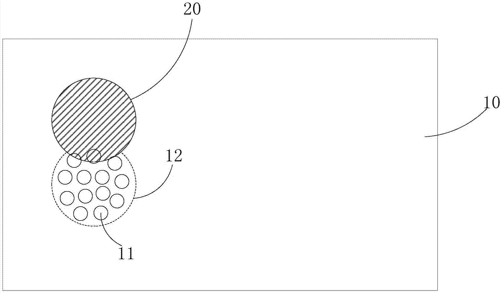
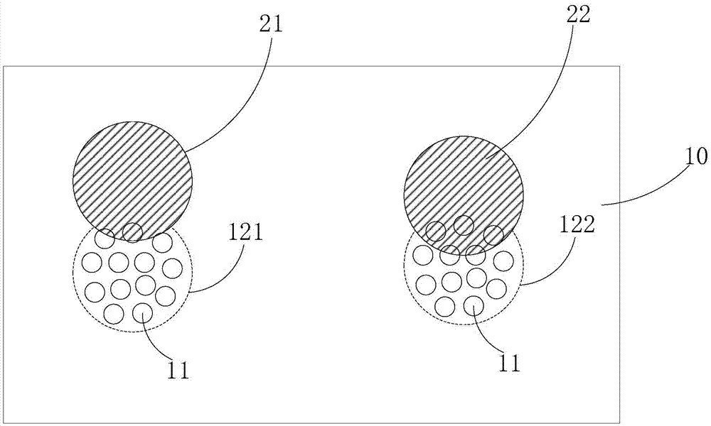
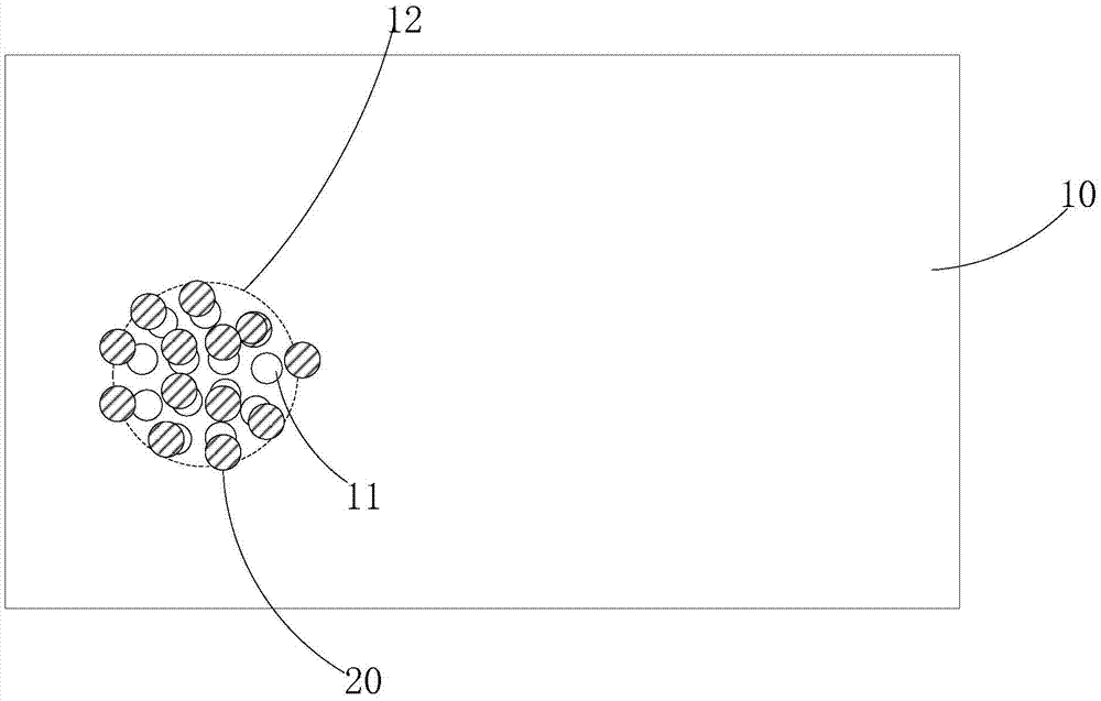
[0033] The vacuum device according to the embodiment of the present invention includes a cavity surrounded by an outer shell, wherein the outer shell includes: a through hole arrangement area, and a plurality of through hole arrangement areas are provided with a plurality of through holes. Hole; a sealing cover that is connected to the outer shell and can move between the first state and the second state;

[0034] Wherein, in the first state, the sealing cover is disposed on the through hole, and the cavity is sealed; in the second state, the sealing cover is moved away from at least part of the through hole , The through hole exposed through the sealing cover is formed as a gas circulation channel of the cavity.

[0035] Compared with...


PUM


Abstract

The invention provides a vacuumizing device and an operation method using the vacuumizing device. The vacuumizing device comprises a cavity defined by an outer shell body. The outer shell body comprises through hole forming areas and sealing covers. A plurality of through holes are formed in the through hole forming areas. The sealing covers are connected with the outer shell body and can move between the first state and the second state. In the fist state, the sealing covers cover the through holes, and the cavity is sealed. In the second state, the sealing covers move to at least part of the through holes. Gas circulation passageways of the cavity are formed by the through holes exposed by the sealing covers. According to the vacuumizing device, part of the through holes can be sealed through the movable sealing covers according to vacuumizing requirements, gas blowing or gas suction can be conducted through the through holes at the same time on this basis, and therefore gas suction efficiency or inflation efficiency can be ensured on the premise of ensuring the leakproofness of the cavity.

Description

Technical field [0001] The invention relates to the technical field of display manufacturing, in particular to a vacuuming device and an operation method using the vacuuming device. Background technique [0002] In the production line of the liquid crystal display, there are a number of processes that require a vacuum chamber, and the vacuum chamber is used to provide a vacuum environment or other gas-filled atmosphere in the manufacturing process of electronic devices. [0003] When the vacuum chamber of the prior art is used to provide a vacuum environment, it is usually provided with only one opening. When vacuuming is required, an air pump is used to perform a vacuum operation through the opening; when used to provide other inflation gas environments Usually, two openings are provided. After the vacuum operation is performed through one opening by the air pump, the air pump is used for the inflation operation through the other hole. [0004] In the vacuum chamber with the above ...

Claims


Application Information

Patent Timeline
Patent Type & Authority Applications(China)
IPC IPC(8): G02F1/13H01L21/67
CPCG02F1/1303H01L21/67121H01L21/67207F16K3/0218F16K3/06
Inventor 孙雪菲李正亮杜建华
Owner BOE TECH GRP CO LTD
Why Eureka
Eureka Blog
Learn More