Combinational logic circuit designing method based on chemical reaction kinetics

A combination logic circuit and chemical reaction technology, applied in the field of DNA logic gate calculation, can solve problems that cannot be simplified and cannot be used

Active Publication Date: 2016-03-30
上海瀚芯实业发展合伙企业(有限合伙)
View PDF1 Cites 6 Cited by
  • Summary
  • Abstract
  • Description
  • Claims
  • Application Information

AI Technical Summary

Problems solved by technology

But for the 2-input XOR gate, the Karnaugh map simplif...

Method used


Image

  • Combinational logic circuit designing method based on chemical reaction kinetics
  • Combinational logic circuit designing method based on chemical reaction kinetics
  • Combinational logic circuit designing method based on chemical reaction kinetics

Examples


example 1

[0257] Taking [0110] as an example, the Karnaugh map is partially mapped according to the above method 1-3, and the CRNs are shown in Tables 2, 3, and 4, respectively.

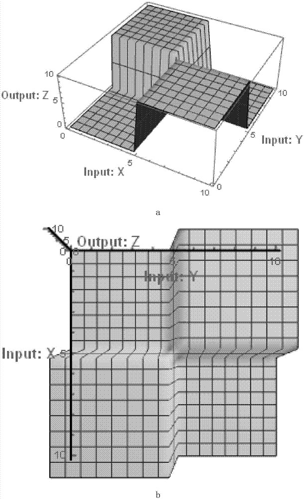
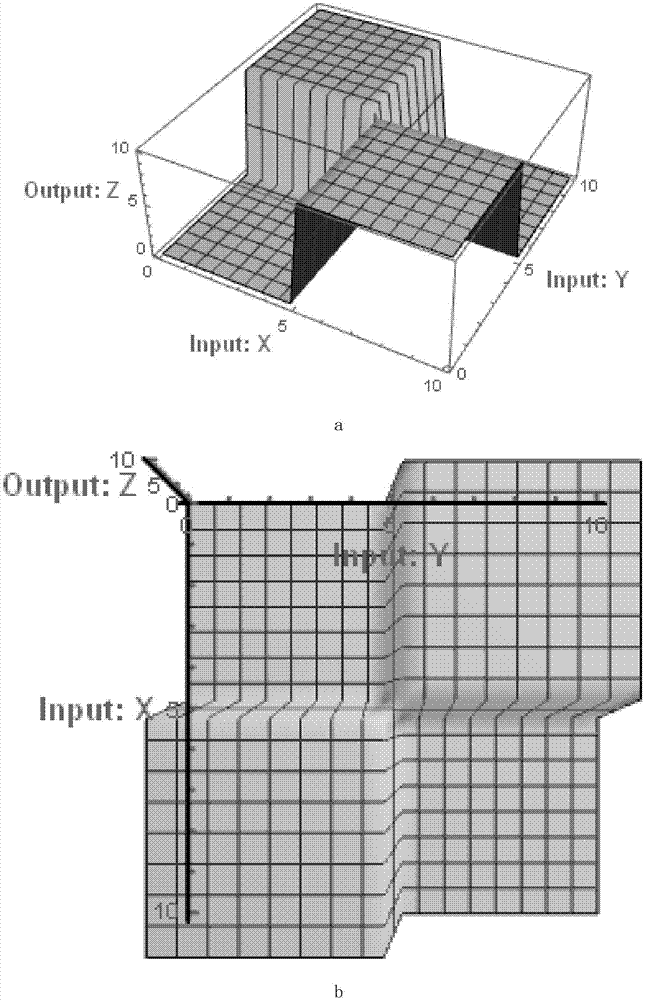
[0258] Simulation using mathematica, initial concentration Z 0 is 10, except for the input signal, the rest are 0, and the input signal X is scanned from 0 to 10 in turn. 1 and Y 1 Concentration (X 0 and Y 0 then change from 10 to 0), the detection output signal Z 1 Concentration, the simulation results see figure 1 , 2 , 3 (a figure is a side view, b figure is a top view).

[0259] Note the striking similarity between the top view and the Karnaugh map.

example 2

[0261] Take [01010101] as an example, Figure 5 Shows the Karnaugh map required for a 3-input, 1-output combinatorial logic. Among them, X, Y, O are input, and Z is output. In addition, the intermediate reactant I generated by Y and O needs to be introduced 1 , I 2 , I 3 , I 4 , and then with the two states X of X 0 、X 1 reaction. Since only small partitions containing logic 1 are constructed, there are 4 small partitions that need to be mapped to the chemical reaction network, thus simplifying the 3-input table into a 2-input table;

[0262] Y 0 + O 0 → Y 0 ...


PUM


Abstract

The invention discloses a combinational logic circuit designing method based on chemical reaction kinetics. A truth table reflecting the logic relationship of input signals and output signals is obtained according to a set logic function; the truth table is partially mapped to a form chemical reaction network CRNs through a karnaugh map, thus realizing the set logic function; according to the method, partial mapping is carried out through the karnaugh map; the number of used chemical reaction equations is reduced without influencing the realized logic function; and the method has universality and is popular and easy to understand.

Description

technical field [0001] The invention relates to a combination logic circuit design method based on chemical reaction kinetics, which belongs to the field of DNA logic gate calculation. Background technique [0002] In 2010, David Soloveichik and others proposed "DNA asuniversal substrate for chemical kinetics" (see literature 1 for details, Soloveichik, D., G. Seelig, and E. Winfree, DNA asuniversal substrate for chemical kinetics. ProcNatlAcadSciUSA, 2010.107 (12): p.5393-8,), to a certain extent from Theoretical proof: For any formal chemical reaction network (CRNs), we can always easily find the physical realization of its corresponding DNA. That is to say, any CRNs we designed can be mapped to the DNA molecular chain replacement reaction; and the DNA molecular chain replacement reaction can be abstracted as A CRN composed of a series of elementary reactions of the form A+B→C+D simplifies the design. [0003] In 2011, Phillip Senum et al proposed "Rate-independent const...

Claims


Application Information

Patent Timeline
IPC IPC(8): G06F19/16G06F19/18
CPCG16B15/00G16B20/00
Inventor 张川戈璐璐钟志伟尤肖虎
Owner 上海瀚芯实业发展合伙企业(有限合伙)
Why Eureka
Try Eureka