Disconnecting switch used for large current ice melting of high-voltage power transmission line

A high-voltage transmission line and isolation switch technology, applied in electrical switches, high-voltage air circuit breakers, circuits, etc., can solve the problem of inability to meet the requirements of large-section wire melting ice, low contact pressure of contacts and fingers, isolation switch ablation, etc. problem, to achieve the effect of good heat dissipation, convenient line access, and improved flow capacity

Inactive Publication Date: 2016-03-30
STATE GRID CORP OF CHINA +2
View PDF10 Cites 2 Cited by
  • Summary
  • Abstract
  • Description
  • Claims
  • Application Information

AI Technical Summary

Problems solved by technology

The ice-melting current is generally realized through the line on the isolating switch. The current level of the current isolating switch is about 6300A, which can meet the ice-melting of the 500kV and below lines. The UHV lines generally use eight-split conductors, and the ice-melting current is generally in the Above 10000A, the current flow level of the existing isolating switch cannot meet the ice melting of large cross-section conductors
The flow capacity of the

Method used


Image

  • Disconnecting switch used for large current ice melting of high-voltage power transmission line
  • Disconnecting switch used for large current ice melting of high-voltage power transmission line
  • Disconnecting switch used for large current ice melting of high-voltage power transmission line

Examples


Example Embodiment

[0020] The present invention will be further described in detail below in conjunction with the drawings and specific embodiments.

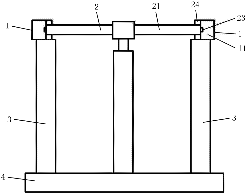
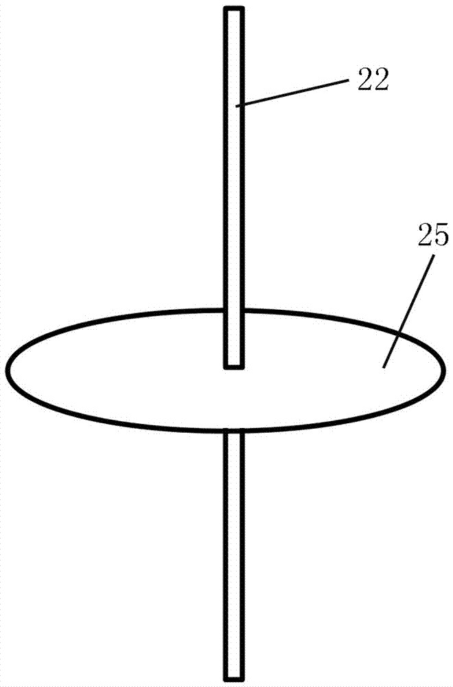
[0021] Such as figure 1 As shown, the isolating switch for high-current ice melting of high-voltage transmission lines of the present invention includes two static contacts 1 respectively connected to the output end of the ice melting device and the line to be melted, and two static contacts for connecting or disconnecting the two static contacts. The on-off control device 2 of the head 1, the two static contacts 1 and the on-off control device 2 are respectively installed on a base 4 through the insulator pillar 3, the on-off control device 2 includes a conduction shaft 21 and rotatably arranged on the insulator pillar 3 on the insulated rotating shaft 22, two static contacts 1 are provided on both sides of the insulated rotating shaft 22, each static contact 1 is provided with a U-shaped groove 11, the conducting shaft 21 is installed on the insulat...


PUM


Abstract

The invention discloses a disconnecting switch used for large current ice melting of a high-voltage power transmission line. Two fixed contacts and an on-off control device are respectively arranged on a pedestal through insulator struts; the on-off control device comprises a conducting shaft and an insulation rotating shaft; two fixed contacts are separately arranged at two sides of the insulation rotating shaft; each fixed contact is provided with a U-shaped groove; the conducting shaft is arranged on the insulation rotating shaft, and the conducting shaft can rotate, so that two ends are respectively embedded into or are simultaneously far away from the U-shaped grooves of the two fixed contacts; a telescopic contact finger and two fixed contact fingers are arranged on two ends of the conducting shaft; the telescopic contact finger can break away from the bottom surfaces of the U-shaped grooves through sliding or be in close contact with the bottom surfaces of the U-shaped groove; the two fixed contact fingers can rotate along with the conducting shaft to break away from or be in close contact with two lateral surfaces of each U-shaped groove; the disconnecting switch further comprises a first driving component used for driving the conducting shaft to rotate along the insulation rotating shaft, a second driving component used for driving the conducting shaft to rotate along the own axis and a third driving component used for driving the telescopic contact finger to carry out concertina movement. The disconnecting switch has the advantages of reasonable structural design, good heat dissipation effect, strong through-current capability and high safe reliability.

Description

technical field [0001] The invention relates to the technical field of electrical engineering equipment, in particular to an isolating switch for high-current high-current melting ice of a high-voltage transmission line. Background technique [0002] my country is one of the countries that are seriously affected by icing disasters in the world. Icing will cause major accidents such as transmission line collapse and insulator flashover. UHV lines are used as backbone grids. Large-scale power outages are caused, which bring serious losses to power grid enterprises and the national economy. Taking 2008 as an example, the ice disaster caused large-scale collapse of towers and disconnection, causing losses to power grid companies as high as tens of billions. At present, the most effective measure to prevent and control ice disasters in the power system is to melt the ice, through the thermal effect of the current, to achieve the purpose of melting the ice. The ice-melting curren...

Claims


Application Information

Patent Timeline
IPC IPC(8): H01H31/02
CPCH01H31/026
Inventor 陆佳政朱远谭艳军李波方针张红先朱思国
Owner STATE GRID CORP OF CHINA
Why Eureka
Try Eureka