Decentralized contact moving contact device

A moving contact, distributed technology, applied in the direction of circuit breaker contacts, circuit breaker components, etc., can solve the problems of time-consuming and labor-intensive, and achieve the effect of improving contact stability, increasing conductive current, and increasing effective contact area

Active Publication Date: 2018-05-22
SUZHOU WANLONG ELECTRIC GROUP
View PDF5 Cites 0 Cited by
  • Summary
  • Abstract
  • Description
  • Claims
  • Application Information

AI Technical Summary

Problems solved by technology

Matched grinding contact end face, when repairing and replacing parts, it is also labor-intensive and time-consuming

Method used


Image

  • Decentralized contact moving contact device
  • Decentralized contact moving contact device
  • Decentralized contact moving contact device

Examples


Embodiment Construction

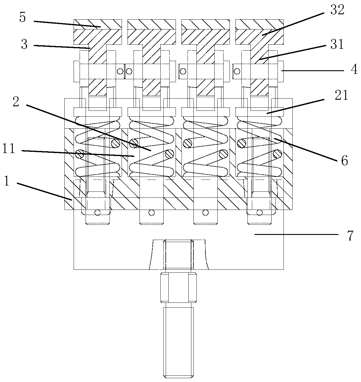
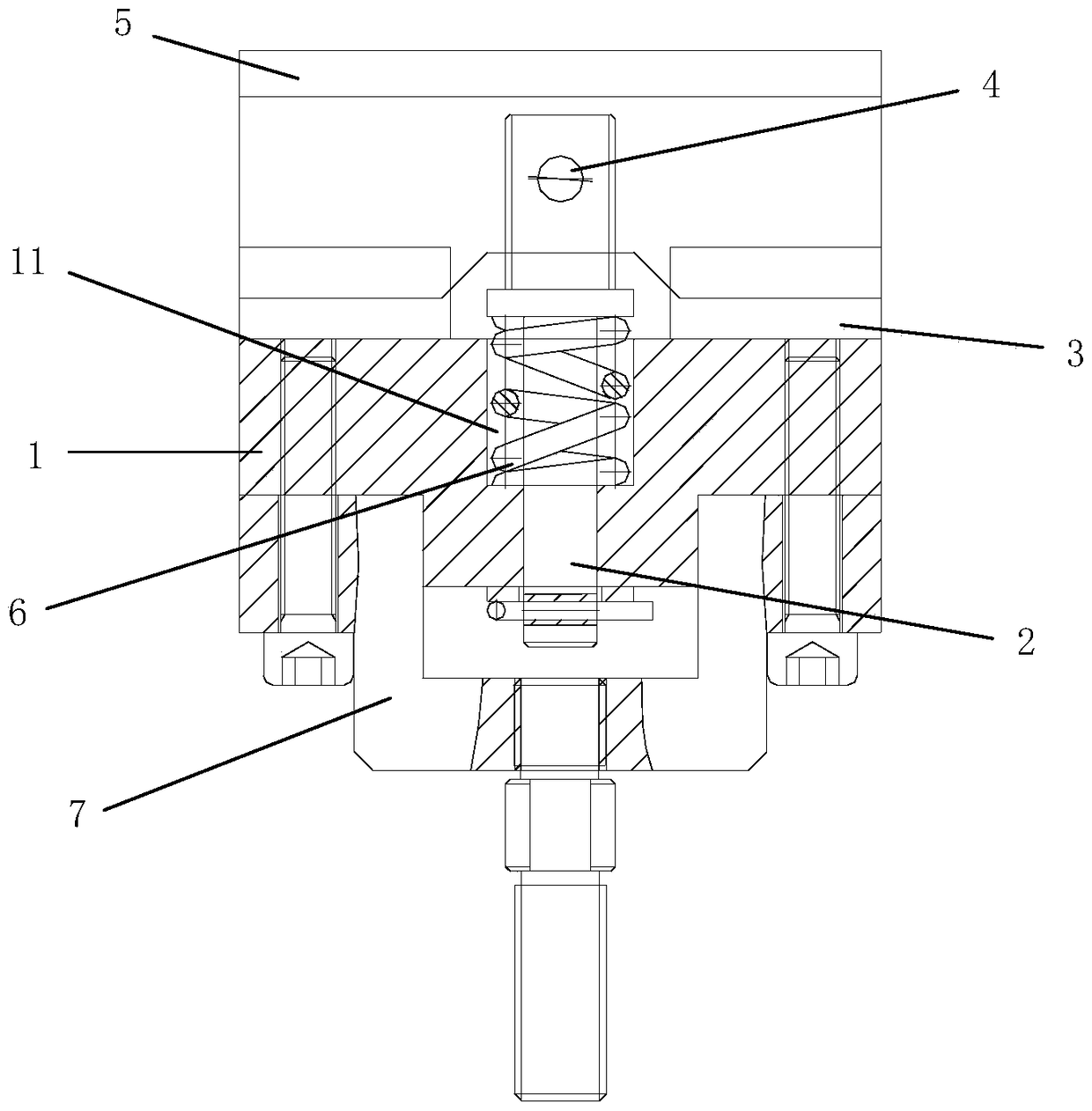
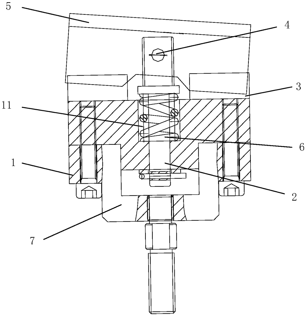
[0020] The present invention will be further described below in conjunction with the accompanying drawings and specific embodiments: Please refer to Figure 1-3 , the present invention relates to a distributed contact moving contact device, and its preferred embodiment includes a contact seat 1, a plurality of contact shafts 2, a plurality of conductive sheet seats 3, a plurality of pivot shafts 4 and a plurality of conductive sheets 5; each The lower end of the contact shaft 2 is installed in the contact seat 1, the upper end of each contact shaft 2 extends upwards out of the contact seat 1, and several contact shafts 2 are distributed at intervals along the length direction of the contact seat 1; each contact The upper end of the shaft 2 is pivotally connected to a corresponding conductive sheet seat 3 through a corresponding pivot shaft 4, and the axis of the pivot shaft 4 is perpendicular to the axis of the contact shaft 2, and the conductive sheet seat 3 can swing around t...


PUM


Abstract

A distributed-contact moving contact device comprises a contact seat, a plurality of contact shafts, a plurality of conductive strip seats, a plurality of pivot shafts and a plurality of conductive strips, wherein the lower end of each contact shaft is arranged in the contact seat, the upper end of each contact shaft is provided with the contact seat in an upward extension way, the plurality of contact shafts are distributed at intervals along a length direction of the contact seat, the upper end of each contact shaft is pivoted with corresponding one of conductive strips by the corresponding pivot shaft, the axial line of the pivot shaft is perpendicular to the axial line of the contact shaft, the conductive strip seats can swing around the pivot shafts, and the conductive strip is arranged on the top surface of each conductive strip seat. With the plurality of conductive strips distributed at intervals, the effective contact area between contact end surfaces is increased, and the conductive current is increased; and moreover, the conductive strip seats can swing relative to the contact shafts, the contact between a moving contact and the contact end surfaces of a busbar also can be conveniently adjusted, so that the contact stability is improved.

Description

technical field [0001] The invention relates to a distributed contact moving contact device. Background technique [0002] The contacts are used to realize high current transmission in the intelligent circuit breaker program-controlled testing station. At present, the contact end faces of contacts on the market are designed to be in contact with two integral end faces, that is, the busbar is an integral end face, and the moving contact is also an integral end face. When the area of ​​the contact end face is large, it is more difficult to ensure the flatness of the end face. The processing precision of the end face is high, and the cost rises sharply; the requirements are general, and the expected effective contact area cannot be obtained. In addition to the difficulty in processing parts, it often takes a long time to ensure good contact between the two contact end surfaces and make up for the lack of processing during assembly. A skilled fitter technician grinds and adjus...

Claims


Application Information

Patent Timeline
Patent Type & Authority Patents(China)
IPC IPC(8): H01H73/04
CPCH01H73/04
Inventor 程玉标刘玉峰朱建高牛永哲
Owner SUZHOU WANLONG ELECTRIC GROUP
Why Eureka
Try Eureka