Main-auxiliary power supply automatic switching system and method

An automatic switching, primary and secondary power supply technology, applied in the direction of emergency power supply arrangements, electrical components, circuit devices, etc., can solve problems such as inconvenient integration, threshold leakage, and complexity, and achieve the effects of improving safety, improving stability, and facilitating integration

Active Publication Date: 2016-03-30
HI TREND TECH SHANGHAI
View PDF5 Cites 20 Cited by
  • Summary
  • Abstract
  • Description
  • Claims
  • Application Information

AI Technical Summary

Problems solved by technology

[0004] Based on the advantages of small conduction loss and easy integration of MOS switching tubes, the system using MOS switching tubes to control the main and auxiliary power supplies for power supply has been widely used. Complicated, resulting in a large chip area, which is not easy to integrate, and there is a risk that it cannot be powered on normally; and in a power supply system that uses a PMOS switch for power switching, because its substrate is always at a high potential, its performance Unstable, and prone to threshold leakage and other issues when turned off

Method used


Image

  • Main-auxiliary power supply automatic switching system and method
  • Main-auxiliary power supply automatic switching system and method
  • Main-auxiliary power supply automatic switching system and method

Examples


Embodiment 1

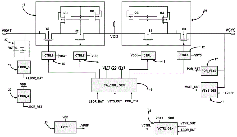
[0042] This application describes a system for automatic switching between primary and secondary power supplies, which can be applied to system-level dual power supplies or even multiple power supplies based on the series double switch switching mode.

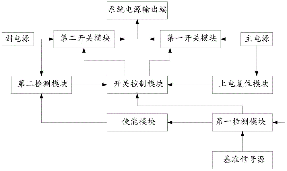
[0043] Such as figure 1 As shown, a system of automatic switching between main and auxiliary power supplies is used in some power systems that require uninterrupted power supply (such as communication terminal equipment (computer rooms, exchange centers, etc.), bank computer systems, surgical equipment, high-precision instruments for measurement And some other important places that require uninterrupted power supply, etc.), including: the main power supply for normal power supply, when the above-mentioned main power supply fails to work, the secondary power supply (which can be one or more One), the first switch module (used to control the disconnection or energization between the main power supply and the electrical system), the s...

Embodiment 2

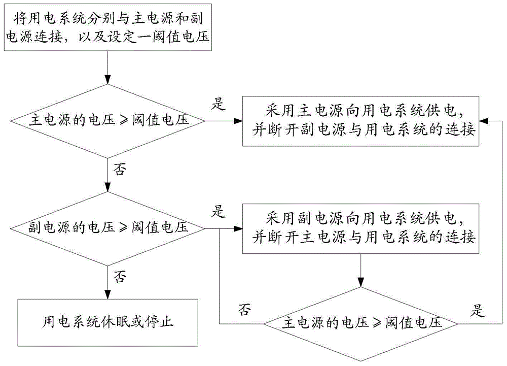
[0057] image 3 This application is a flow chart of a method for automatic switching between primary and secondary power sources; image 3 As shown, a method for switching between primary and secondary power sources can be applied to the above-mentioned automatic switching system between primary and secondary power sources, and includes the following steps:

[0058] First, connect the main power source and the secondary power source to the power consumption system respectively (so that both the secondary power source and the main power source can supply power to the power consumption system), and set the threshold voltage for the normal operation of the power consumption system.

[0059] Secondly, detect whether the voltage of the main power source is greater than or equal to the threshold voltage; if the voltage of the main power source is greater than or equal to the threshold voltage, disconnect the secondary power source from the electrical system, and use the main power source t...


PUM


Abstract

The invention discloses a main-auxiliary power supply automatic switching system and method, and relates to a power switching system and method. A detection module is set for detecting in real time whether the voltage of a main power supply and the voltage of an auxiliary power supply meet the power utilization demands or not. A switching control circuit is used for automatically achieving the switching between the main power supply and the auxiliary power supply, so as to guarantee that a power supply connected with a power utilization system meets a power utilization requirement. Moreover, the system is simple in circuit, is convenient to integrate, employs a cross coupling PMOS switching module, effectively improves the stability of a switching circuit, and further improves the safety of a power switching system and the power supply efficiency of the power switching system.

Description

Technical field [0001] The invention relates to a power supply switching system and method, in particular to a main and auxiliary power supply automatic switching system and method. Background technique [0002] With the development of society, various industries have higher and higher requirements for the reliability of power supply. For example, communication terminal equipment, bank computer systems, surgical equipment, high-precision measuring instruments and some important places require uninterrupted power supply. [0003] In order to meet people's requirements for the reliability of the power supply system, the traditional dual power supply system using diodes to control the main power supply and the auxiliary power supply is used for power supply, but its work efficiency is low and its application is very limited. [0004] Based on the advantages of MOS switch tube with low conduction loss and easy integration, the system that uses MOS switch tube to control the main and auxi...

Claims


Application Information

Patent Timeline
Patent Type & Authority Applications(China)
IPC IPC(8): H02J9/06
Inventor 渠宁郎君佘龙代建宾萧经华
Owner HI TREND TECH SHANGHAI
Why Eureka
Try Eureka